
With measured data the true orientation distribution function (ODF) is unknown. A reconstruction can therefore be judged by how well it reproduces the measurement, but that is also the data it was fitted to. Simulation removes this circularity. Start from a known ODF, compute the pole figures it would produce, add counting noise, reconstruct, and compare the result with the known model.
This page runs that controlled experiment once. It then asks a practical question: how many pole figures does this particular reconstruction need? The model components are introduced in ODF Modelling, the forward projection in Pole Figures of an ODF, and the inverse problem in ODF Reconstruction.
A plotting convention states how a reference frame is laid out on screen. Here specimen Y points up and specimen X points right; the convention does not rotate the specimen or the ODF.
plottingConvention.default('y↑→x');A known test ODF
The orthorhombic model contains six components. Half of the volume is uniform, three fibre components contribute 0.05 each, and two unimodal components contribute 0.05 and 0.30. The large uniform portion makes the inversion deliberately difficult because independently scaled pole figures constrain that portion least.
cs = crystalSymmetry('orthorhombic');
mod1 = orientation.byAxisAngle(xvector,45*degree,cs);
mod2 = orientation.byAxisAngle(yvector,65*degree,cs);
model_odf = 0.5*uniformODF(cs) + ...
  0.05*fibreODF(Miller(1,0,0,cs),xvector,'halfwidth',10*degree) + ...
  0.05*fibreODF(Miller(0,1,0,cs),yvector,'halfwidth',10*degree) + ...
  0.05*fibreODF(Miller(0,0,1,cs),zvector,'halfwidth',10*degree) + ...
  0.05*unimodalODF(mod1,'halfwidth',15*degree) + ...
  0.3*unimodalODF(mod2,'halfwidth',25*degree);

plot(model_odf,'sections',6,'silent','sigma','minmax')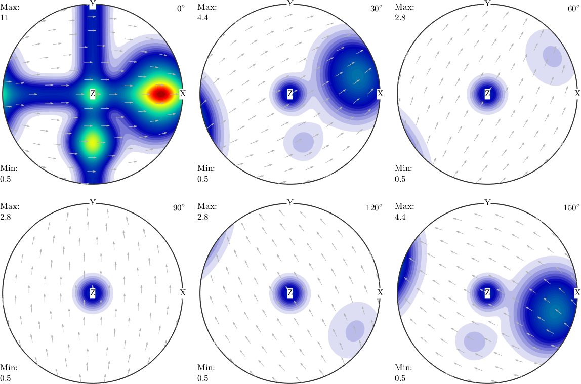
The sigma sections separate the compact maxima of the two unimodal components from the extended bands of the three fibres. The uniform half of the model is the common baseline beneath those features rather than a separate peak.
Simulating the measurement
Three choices determine the simulated measurement: which lattice planes are measured, which specimen directions are sampled, and how many counts are expected. Superposition coefficients may also be supplied when diffraction peaks from several lattice planes overlap.
The seven lattice directions below are kept in a deliberate order. The final experiment adds their pole figures from left to right.
h = [Miller(1,1,1,cs),Miller(1,1,0,cs),Miller(1,0,1,cs),Miller(0,1,1,cs),...
  Miller(1,0,0,cs),Miller(0,1,0,cs),Miller(0,0,1,cs)];
They are sampled on a regular grid with 5 degree spacing.
r = regularS2Grid('resolution',5*degree); calcPoleFigure evaluates the ODF for every lattice direction and specimen direction. Its printed summary confirms the seven pole figures and their sampling grids.
pf = calcPoleFigure(model_odf,h,r)pf = PoleFigure (y↑→x)
crystal symmetry : mmm
h = (111), r = 72 × 37 points
h = (110), r = 72 × 37 points
h = (101), r = 72 × 37 points
h = (011), r = 72 × 37 points
h = (100), r = 72 × 37 points
h = (010), r = 72 × 37 points
h = (001), r = 72 × 37 pointsAdding counting noise
The values above are exact pole densities. A diffraction measurement counts quanta, so its counting error is commonly modelled by a Poisson distribution. At a point with pole density \(P_h(r)\), the call below draws a count with mean \(1000 P_h(r)\). Thus 1000 is an intensity scale, not the same mean count at every point. No background is added in this example.
noisepf makes the absolute fluctuations larger at bright points but their relative size smaller.
pf = noisepf(pf,1000);

plot(pf)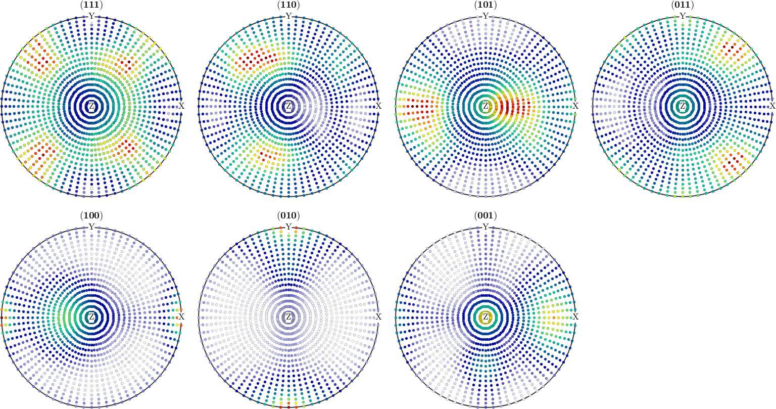
The seven panels retain the smooth bands and maxima imposed by the model, but individual grid values now fluctuate. The fluctuations are most conspicuous relative to the signal in the darker parts of each panel.
Reconstructing and comparing
The simulated counts can be passed to the ordinary reconstruction. The scale of each pole figure is estimated as part of that inversion.
odf = calcODF(pf,'silent');

plot(odf,'sections',6,'silent','sigma','minmax')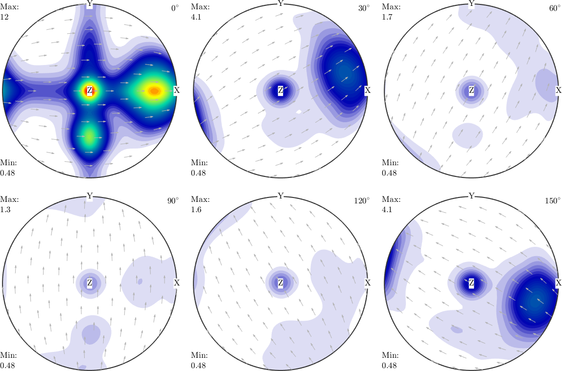
Compared with the model sections above, the compact maxima and fibre bands are in the same places and have similar shapes. The minimum and maximum labels expose differences in amplitude that independent colour scales could hide.
calcError compares the two normalized ODFs on a 5 degree orientation grid. Its default ODF-to-ODF measure is the L1 distance divided by two, which is the minimum volume fraction that would have to be moved to turn one distribution into the other.
modelError = calcError(odf,model_odf,'resolution',5*degree);
fprintf('L1 reconstruction error: %.4f\n',modelError)
L1 reconstruction error: 0.0836The error is 8.3 percent of the volume. A real experiment has no known model ODF against which this number can be computed, which is the reason for simulating.
How many pole figures are needed
Each additional pole figure supplies more equations to an underdetermined inverse problem. The error may therefore fall as figures are added, then level off once the remaining ambiguity is not resolved by these data. Noise and regularisation mean that the decrease need not be monotonic.
The following experiment reconstructs from the first pole figure, the first two, and so on. Each subset is reconstructed both without and with ghost correction.
e = zeros(pf.numPF,2);
for i = 1:pf.numPF

  odf = calcODF(pf({1:i}),'silent','noGhostCorrection');
  e(i,1) = calcError(odf,model_odf,'resolution',2.5*degree);
  odf = calcODF(pf({1:i}),'silent');
  e(i,2) = calcError(odf,model_odf,'resolution',2.5*degree);

end

errorByCount = table((1:pf.numPF)',e(:,1),e(:,2),...
  'VariableNames',{'poleFigures','withoutGhostCorrection',...
  'withGhostCorrection'})

close all;
plot(1:pf.numPF,e,'o-','LineWidth',2)
xlabel('Number of pole figures');
ylabel('L1 reconstruction error');
xticks(1:pf.numPF);
ylim([0 0.35]);
grid on
legend({'Without ghost correction','With ghost correction'});
errorByCount =
7×3 table
poleFigures withoutGhostCorrection withGhostCorrection
___________ ______________________ ___________________
1 0.30164 0.29932
2 0.24801 0.24076
3 0.15056 0.13944
4 0.12724 0.11106
5 0.14523 0.12812
6 0.1155 0.10171
7 0.1027 0.083678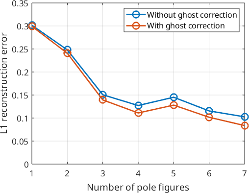
Both curves fall steeply from one pole figure to four: the error with ghost correction drops from 0.299 to 0.110. They then flatten, with a bump when the fifth pole figure is added. In this experiment, four pole figures capture most of the recoverable information, and which four are chosen matters more than simply increasing their number.
The corrected curve is lower at every count, though not by much: 0.083 against 0.102 at seven pole figures, and almost no difference at one. Ghost correction addresses a specific defect by estimating the uniform portion. This model has a large uniform portion by construction; see The Ghost Effect for why it is difficult to recover.
Four is not a general minimum. The result depends on this ODF, crystal symmetry, ordered set of lattice directions, full sampling grid, count scale, and reconstruction settings. The bump at five is a useful warning: the solver fits noisy pole figures, not the hidden model used to score it.
What this simulation leaves out
This controlled example isolates counting noise and the ambiguity of the inversion. Real pole figures may also have incomplete angular coverage, background, defocusing, uncertain normalization, outliers, and overlapping diffraction peaks. Simulation tests the reconstruction under the effects included in the model; it does not validate corrections that were omitted.
Further Reading
- H.-J. Bunge, Texture Analysis in Materials Science: Mathematical Methods, Butterworths, English ed., 1982. This is the classical treatment of pole figures, ODF inversion, and reconstruction ambiguity.
- R. Hielscher and H. Schaeben, A novel pole figure inversion method: specification of the MTEX algorithm, Journal of Applied Crystallography 41 (2008), 1024--1037. It derives the estimator used here from a Poisson model of diffraction counts.
- S. Matthies and G. W. Vinel, On the reproduction of the orientation distribution function of textured samples from reduced pole figures using the conception of a conditional ghost correction, physica status solidi (b) 112 (1982), K111--K114.
- ASTM International, ASTM E81-96(2024): Standard Test Method for Preparing Quantitative Pole Figures. It covers experimental procedures for complete and partial quantitative X-ray pole figures.
Next
The next page, The Ghost Effect, shows why distinct ODFs can produce identical pole figures. Continue with Ghost Correction for the correction compared here, then the Santa Fe example for the same comparison on a standard model ODF.
Citing this page.
This page is part of the documentation of
MTEX, a free and open
source MATLAB toolbox for analyzing and modeling crystallographic textures.
It was written by The MTEX Developers and is published at
https://mtex-toolbox.github.io/PoleFigureSimulation.html.
If you use MTEX, or reuse text or figures from this page, in your research,
please cite
F. Bachmann, R. Hielscher, H. Schaeben: Texture Analysis with MTEX - Free and Open Source Software Toolbox, Solid State Phenomena 160 (2010), 63-68. 10.4028/www.scientific.net/SSP.160.63
BibTeX
@article{bachmann2010mtex,
  author  = {F. Bachmann and R. Hielscher and H. Schaeben},
  title   = {Texture Analysis with MTEX - Free and Open Source Software Toolbox},
  journal = {Solid State Phenomena},
  volume  = {160},
  pages   = {63-68},
  year    = {2010},
  doi     = {10.4028/www.scientific.net/SSP.160.63},
  url     = {https://doi.org/10.4028/www.scientific.net/SSP.160.63}
}
Other papers describing specific MTEX methods are listed under Publications — please cite the one that best fits your application. The MTEX source code is licensed under the GNU General Public License v2.0; the text and figures of this documentation are licensed under CC BY 4.0, which permits reuse — including by automated systems — provided The MTEX Developers and this page are credited.