
A contour line joins points with the same value. It lets a reader take a number from a figure instead of guessing it from a colour. Add contours when a value will be quoted in the text. Label them when more than one level matters.
Color Mapping defines a contour level and explains why separate plots need the same explicit levels. This page shows how to draw, overlay, and label those levels. Plot Types compares contour plots with scatter and smooth plots.
Start with a smooth spherical function
The function used here has no physical meaning. It stands in for a pole figure, an inverse pole figure, a Schmid factor map, a Taylor factor map, or any other function defined on the sphere.
plottingConvention.default('y↑→x');
sF = 0.01 + 10*S2Fun.smiley
levels = -4:5;

plot(sF,'upper')
mtexColorMap blue2red
mtexColorbar
sF = S2FunHarmonic (y↑→x)
bandwidth: 128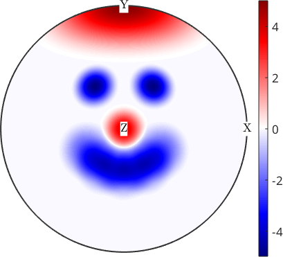
The smooth colours make the face easy to recognize, and the colour bar gives the approximate values. They do not mark the exact positions where the function reaches an integer level.
Choose filled bands or lines
'contourf' replaces smooth shading by filled bands. Every value between two neighboring levels receives one colour. The bands are easy to scan, but they deliberately hide variation within each interval.
plot(sF,'contourf',levels,'upper')
mtexColorMap blue2red
mtexColorbar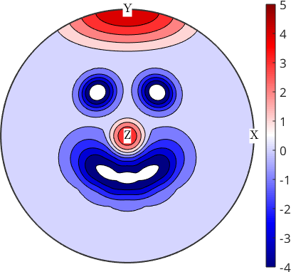
The face is now quantized into one-unit bands from -4 to 5. Use 'contour' instead when only the boundaries are needed. The explicit levels vector also makes this plot comparable with another figure using the same vector.
Overlay contour lines on smooth colours
Contour lines can be laid over a smooth plot instead of replacing it. This keeps the continuous colour variation while making exact levels visible.
close all
plot(sF,'upper')
mtexColorMap blue2red
mtexColorbar

hold on

hContour = plot(sF,'contour',levels,...
  'lineWidth',2,'lineColor','k')

hold off
hContour =
Contour with properties:
EdgeColor: [0 0 0]
LineStyle: '-'
LineWidth: 2
FaceColor: 'none'
LevelList: [-4 -3 -2 -1 0 1 2 3 4 5]
XData: [91×361 double]
YData: [91×361 double]
ZData: [91×361 double]
Use GET to show all properties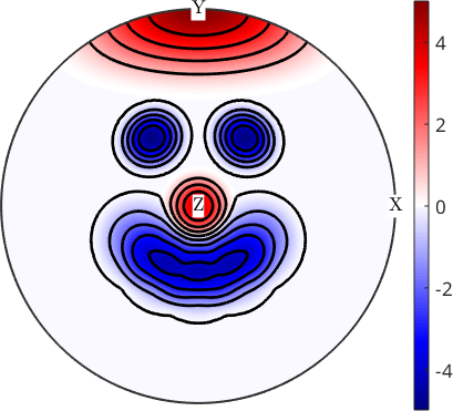
The black curves outline the same integer bands without covering the smooth field. The red and blue regions remain visible between the lines.
Label selected contours
A single-axis contour plot returns a MATLAB contour handle. Its ContourMatrix and the handle itself can be passed to MATLAB's clabel command. Label the levels needed for the reading instead of every line, because repeated labels quickly obscure the map.
levels2label = [-2,0:5];
clabel(hContour.ContourMatrix,hContour,levels2label,'FontSize',15)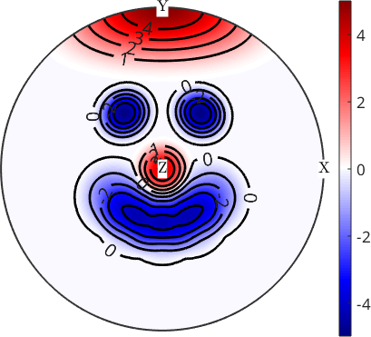
The labels now make the sign and size of the main features readable. The unlabelled contours still show their shapes without adding more text.
Label contours on several axes
The same method applies to real pole figures. A multi-axis plotting command returns several contour handles, so there is no single handle to pass to clabel. 'ShowText','on' labels the drawn levels on every axis without requiring a loop over those handles.
mtexdata dubna
odf = calcODF(pf,'silent')

h = pf{4:5}.h;
plotPDF(odf,h)
mtexColorMap LaboTeX
mtexColorbar

hold on
plotPDF(odf,h,'contour',1:2:15,...
  'lineColor','black','lineWidth',2,'ShowText','on')
hold off
pf = PoleFigure (y↑→x)
crystal symmetry : Quartz (321, X||a*, Y||b, Z||c)
h = (022̅1), r = 72 × 19 points
h = (101̅0), r = 72 × 19 points
h = (101̅1)(011̅1), r = 72 × 19 points
h = (101̅2), r = 72 × 19 points
h = (112̅0), r = 72 × 19 points
h = (112̅1), r = 72 × 19 points
h = (112̅2), r = 72 × 19 points
odf = SO3FunRBF (Quartz → y↑→x)
multimodal components
kernel: de la Vallee Poussin, halfwidth 5°
center: 19848 orientations, resolution: 5°
weight: 1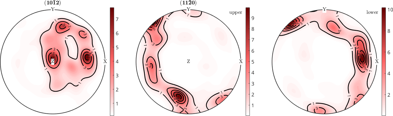
The two requested pole-figure entries expand under crystal symmetry to three plotted panels. Every panel carries the same levels from 1 to 15 in steps of 2, so the fields can be compared line by line. Explicit levels prevent each panel from choosing a different numerical scale.
References
- S. R. Midway, Principles of Effective Data Visualization, Patterns 1 (2020), 100141, explains how direct labels and consistent visual scales support comparisons between plots.
Next
Continue with Transparency to reveal overlapping markers and superposed maps without hiding either layer.
Citing this page.
This page is part of the documentation of
MTEX, a free and open
source MATLAB toolbox for analyzing and modeling crystallographic textures.
It was written by The MTEX Developers and is published at
https://mtex-toolbox.github.io/ContourPlots.html.
If you use MTEX, or reuse text or figures from this page, in your research,
please cite
F. Bachmann, R. Hielscher, H. Schaeben: Texture Analysis with MTEX - Free and Open Source Software Toolbox, Solid State Phenomena 160 (2010), 63-68. 10.4028/www.scientific.net/SSP.160.63
BibTeX
@article{bachmann2010mtex,
  author  = {F. Bachmann and R. Hielscher and H. Schaeben},
  title   = {Texture Analysis with MTEX - Free and Open Source Software Toolbox},
  journal = {Solid State Phenomena},
  volume  = {160},
  pages   = {63-68},
  year    = {2010},
  doi     = {10.4028/www.scientific.net/SSP.160.63},
  url     = {https://doi.org/10.4028/www.scientific.net/SSP.160.63}
}
Other papers describing specific MTEX methods are listed under Publications — please cite the one that best fits your application. The MTEX source code is licensed under the GNU General Public License v2.0; the text and figures of this documentation are licensed under CC BY 4.0, which permits reuse — including by automated systems — provided The MTEX Developers and this page are credited.