
A plot type determines what the marks in a figure mean. A marker can stand for one sampled value, a contour can join equal values of a function, and a smooth plot can show the function between those levels. Choosing among them is therefore part of the analysis, not a cosmetic decision.
This page compares five plot types used throughout MTEX: scatter, contour, filled contour, smooth and line plots. Start by deciding whether the object contains discrete samples or represents a function that may be evaluated between samples.
plottingConvention.default('y↑→x');The example data
The examples use one model orientation distribution function (ODF), one pole figure evaluated from it on a discrete grid, and 100 orientations sampled from it. The ODF is a function. The other two objects contain discrete values derived from that function.
cs = crystalSymmetry('-3m');
odf = fibreODF(Miller(1,1,0,cs),zvector);
pf = calcPoleFigure(odf,Miller(1,0,0,cs),equispacedS2Grid('antipodal'));
ori = discreteSample(odf,100);Scatter plots
A scatter plot draws one marker per data point and asserts nothing about the space between them. It is the direct choice for sampled orientations: the eye can see both clustering and unsampled parts of orientation space.
close all
scatter(ori)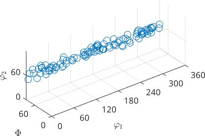
Each marker in the figure is one of the 100 sampled orientations. No continuous density has been reconstructed from them.
Vectors, Miller indices and spherical grids use the same marker idea in a spherical projection. The marker is controlled by the usual MATLAB Scatter properties:
Marker, MarkerSize, MarkerFaceColor, MarkerEdgeColor
plot(zvector,'Marker','p','MarkerSize',15,'MarkerFaceColor','red','MarkerEdgeColor','black')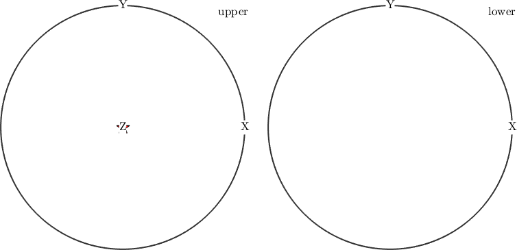
The pentagon marks the specimen z direction. Changing its shape and colours changes only the annotation, not the direction it represents.
A marker may carry a label, with the text properties of Text properties:
Label, Color, BackgroundColor, FontSize
plot([Miller(1,1,1,cs),Miller(-1,1,1,cs)],...
  'label',{'X','Y'},...
  'Color','blue','BackgroundColor','yellow','FontSize',20,'grid')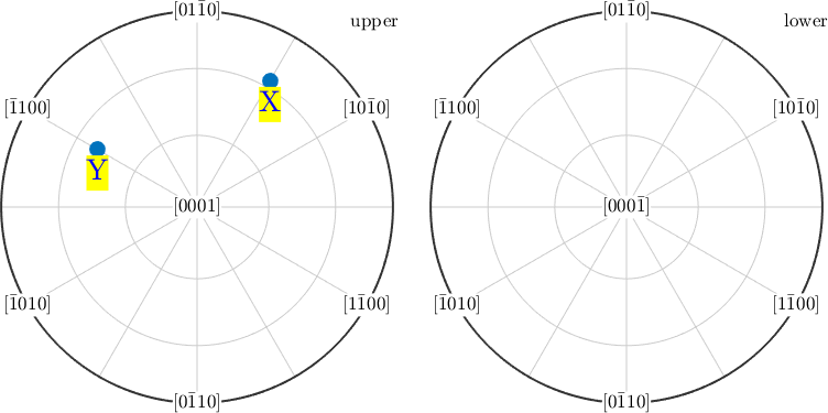
The two labels identify the projected crystal directions; the grid makes their positions on the sphere readable.
A PoleFigure also stores one intensity for each direction on a discrete grid. For measured data, each dot corresponds to a measurement direction. The synthetic pole figure below instead uses the grid supplied to calcPoleFigure, but the scatter plot exposes that grid in the same way.
plot(pf)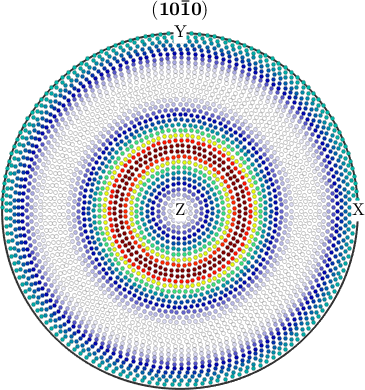
The dots reveal where values exist and how densely the pole figure was sampled. A smooth plot would hide this sampling pattern.
Contour plots
A contour joins positions at the same function value. Use contours when levels must be located or compared. MTEX can choose the levels, or they can be given explicitly. Here they run from 0 to 4 in steps of 0.5 multiples of a uniform orientation distribution:
plotPDF(odf,Miller(1,0,0,cs),'contour',0:0.5:4,'antipodal')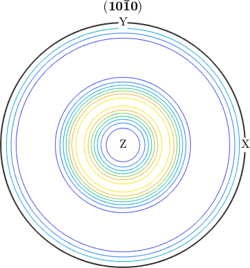
The nested lines locate the peak without implying intermediate colour bands. Fixing the same levels in several figures makes their shapes and magnitudes comparable. Further options are the MATLAB Contour properties.
Filled contour plots
'contourf' fills the bands between contour lines. The colour blocks are easy to scan, but they quantize the function: every value in one band gets the same colour, so a gentle gradient becomes a staircase.
plotPDF(odf,Miller(1,0,0,cs),'contourf','antipodal')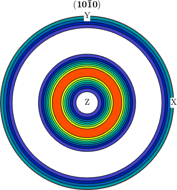
Compared with the line contours, the peak occupies a more obvious area. Its internal variation is hidden inside the filled bands.
Smooth plots
Smooth shading is the default when a function is plotted, as plotPDF does for an ODF here. Measured PoleFigure data is drawn as a scatter instead, which is what the figure above shows. Smooth shading assigns a colour at every evaluation point, without contour boundaries. 'resolution' controls the angular spacing of that evaluation grid; it does not increase the resolution of measured data.
plotPDF(odf,Miller(1,0,0,cs),'antipodal','resolution',10*degree)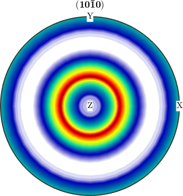
The colour now changes continuously across the peak, while the coarse evaluation grid limits the detail. Compare this with the pole-figure scatter plot: this figure evaluates a function on a grid chosen for the drawing, whereas a measured pole figure has values only on the diffractometer's measurement grid. They may look similar but mean different things.
Line plots
A line plot shows a one-dimensional section through a function. Examples include values along an orientation fibre, values over harmonic degrees, and a section through a kernel. The usual line specification options apply.
f = fibre(Miller(1,0,0,cs),xvector);

plot(odf,f,'linewidth',2,'linestyle','-.','figSize','small')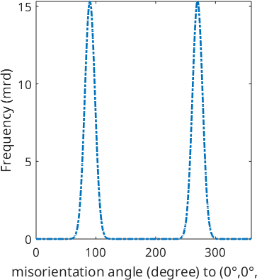
The horizontal coordinate follows the fibre and the vertical coordinate gives the ODF value. This makes the peak's height, width and any shoulder easier to judge than in a colour-coded spherical plot.
Choosing a plot type
Use scatter plots to preserve discrete samples and their gaps. Use line or contour plots when positions and values must be read against axes or levels. Use filled contours for a compact view of bands, and smooth shading for continuous variation. When figures will be compared, keep their contour levels or colour ranges fixed. Contour Plots develops the contour options, and Combined Plots shows how to arrange related views.
Further reading
Cleveland and McGill, Graphical Perception, connects graphical choices with the accuracy of visual decoding. Wilke's Fundamentals of Data Visualization organizes plot choice by the message a figure should convey.
Citing this page.
This page is part of the documentation of
MTEX, a free and open
source MATLAB toolbox for analyzing and modeling crystallographic textures.
It was written by The MTEX Developers and is published at
https://mtex-toolbox.github.io/PlotTypes.html.
If you use MTEX, or reuse text or figures from this page, in your research,
please cite
F. Bachmann, R. Hielscher, H. Schaeben: Texture Analysis with MTEX - Free and Open Source Software Toolbox, Solid State Phenomena 160 (2010), 63-68. 10.4028/www.scientific.net/SSP.160.63
BibTeX
@article{bachmann2010mtex,
  author  = {F. Bachmann and R. Hielscher and H. Schaeben},
  title   = {Texture Analysis with MTEX - Free and Open Source Software Toolbox},
  journal = {Solid State Phenomena},
  volume  = {160},
  pages   = {63-68},
  year    = {2010},
  doi     = {10.4028/www.scientific.net/SSP.160.63},
  url     = {https://doi.org/10.4028/www.scientific.net/SSP.160.63}
}
Other papers describing specific MTEX methods are listed under Publications — please cite the one that best fits your application. The MTEX source code is licensed under the GNU General Public License v2.0; the text and figures of this documentation are licensed under CC BY 4.0, which permits reuse — including by automated systems — provided The MTEX Developers and this page are credited.