
A colour range is the numerical interval represented by a plot's colours. Its lower and upper limits receive the end colours of the colormap. Two plots can be compared by colour only when they use the same range and the same colormap.
This page shows how MTEX chooses the range, how to fix it, and how a colormap translates values within that range into colours. Legends for discrete objects and colour keys for directions were distinguished on Legends.
plottingConvention.default('y↑→x');Create two quantities to compare
An orientation distribution function (ODF) describes the relative frequency of crystal orientations. This model ODF supplies two simulated pole figures whose densities can be compared.
cs = crystalSymmetry('-3m');
odf = fibreODF(Miller(1,1,0,cs),zvector)
pf = calcPoleFigure(odf,[Miller(1,0,0,cs),Miller(1,1,1,cs)],...
  equispacedS2Grid('points',500,'antipodal'));
odf = SO3FunCBF (3̅m1 → y↑→x)
kernel: de la Vallee Poussin, halfwidth 10°
fibre : (112̅0) || 0,0,1
weight: 1The default range is tight and per axis
Without a 'colorRange' option, MTEX uses 'tight'. Each axis spans the range of its own data. This uses the available colours fully, but it does not guarantee that colours are comparable between axes.
close all
plot(pf)
mtexColorbar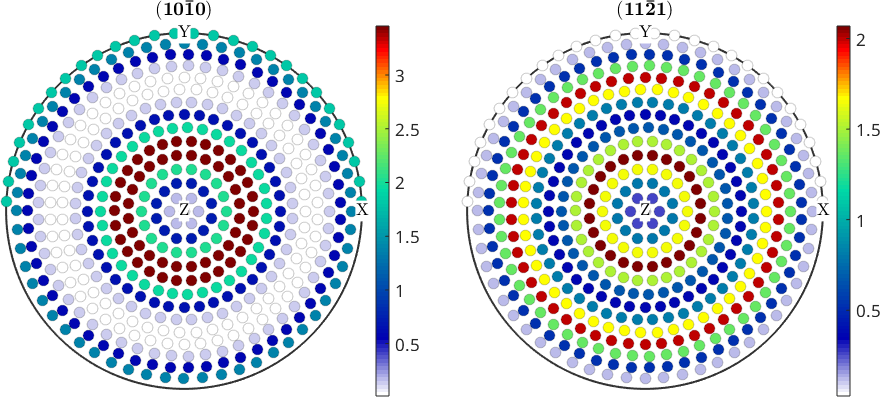
Read the two colour bars before comparing the patterns. The \((100)\) panel reaches approximately 3.5 multiples of a uniform distribution (mrd), whereas the \((111)\) panel reaches approximately 2.1 mrd. The same colour therefore denotes a different pole density in each panel. Nothing in the maps alone warns about that mismatch.
Use one range for one figure
'colorRange','equal' chooses the smallest common range containing the tight range of every axis in the figure.
plot(pf,'colorRange','equal')
mtexColorbar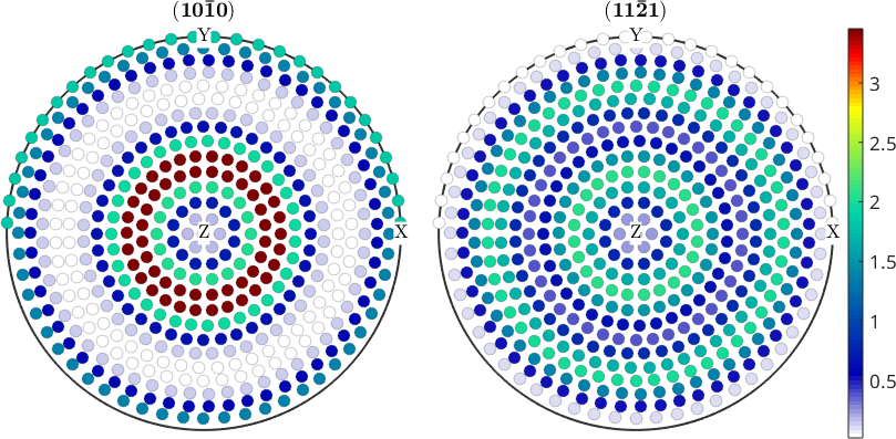
One colour bar now serves the figure, and both panels run to approximately 3.5 mrd. The \((111)\) panel is visibly paler. The common range reveals its lower density, which the separate tight ranges hid.
Fix one range across separate figures
Separate figures cannot discover each other's limits. State the same numerical range in each plotting command. Here the original ODF and a mixture containing half uniform ODF both use the interval from 0 to 4 mrd.
close all
plotPDF(odf,[Miller(1,0,0,cs),Miller(1,1,1,cs)],...
  'colorRange',[0 4],'antipodal');
mtexColorbar

figure
odfMixed = 0.5 * odf + 0.5 * uniformODF(cs);
plotPDF(odfMixed,[Miller(1,0,0,cs),Miller(1,1,1,cs)],...
  'colorRange',[0 4],'antipodal');
mtexColorbar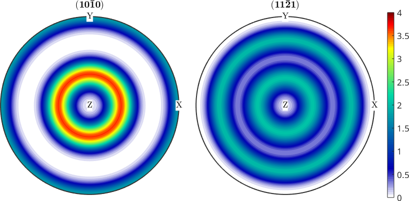
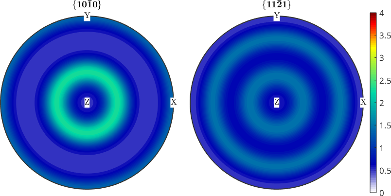
Mixing with the uniform ODF halves the density contrast above 1 mrd. Because the figures share a range, the second texture looks weaker. Tight ranges would map these two affinely related fields to the same colours and make them look identical.
Use explicit contour levels
A contour level is a value at which a contour line or colour boundary is drawn. Explicit levels take the place of an explicit colour range for a contour plot. Reusing the levels makes separate contour plots comparable.
close all
plotPDF(odf,[Miller(1,0,0,cs),Miller(1,1,1,cs)],...
  'contourf',0:1:5,'antipodal')
mtexColorbar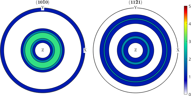
Change the range after plotting
setColorRange adjusts a figure that has already been drawn. This is convenient when the useful limits become clear only after inspecting the data.
setColorRange([0.38 3.9])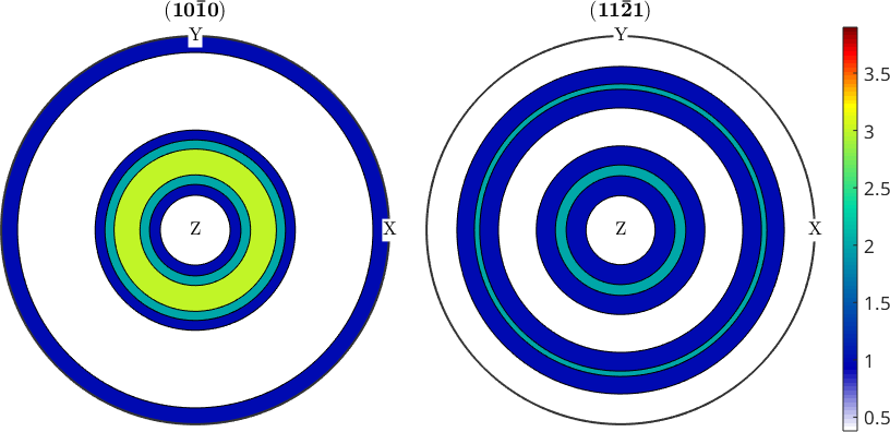
The colour bar now spans 0.38 to 3.9 mrd. Values outside that interval use an end colour. Existing contour boundaries stay at their original levels; changing the colour range does not recompute the contours.
Use a logarithmic scale
A sharp texture puts most values near zero and a few at much larger values. A linear scale can then show one small bright area against an almost empty background. 'logarithmic' spreads the positive low values across more colours. Its lower colour-range limit must be positive.
close all
plotPDF(odf,[Miller(1,0,0,cs),Miller(1,1,1,cs)],...
  'antipodal','logarithmic')
setColorRange([0.01 12]);
mtexColorbar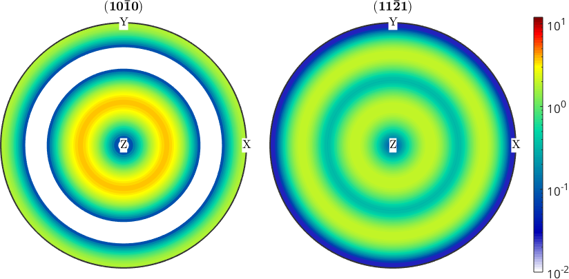
Weak parts of the pole figures now show structure. The colour bar is no longer linear, so equal distances in colour no longer represent equal differences in density. That loss of linear distance is the trade-off for making weak structure visible.
Choose a colormap
A colormap is the ordered set of colours assigned across the colour range. mtexColorMap sets it for a figure. MTEX supplies white2black, blue2red, and LaboTeX in addition to MATLAB colormaps.
plotPDF(odf,[Miller(1,0,0,cs),Miller(1,1,1,cs)],'antipodal')
mtexColorMap white2black
mtexColorbar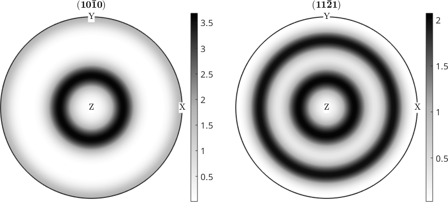
Colormap choice is not decoration. A monotone map such as white2black is an honest default for a density, which has no natural middle. A diverging map such as blue2red suits a quantity with a meaningful middle, such as signed curvature or the difference between two pole figures. Its neutral colour lies at the middle of the range. Set that range symmetrically, or the neutral colour marks a meaningless value.
Use different colormaps in one figure
Without an axes handle, mtexColorMap changes every axis in the figure. Pass an axes handle to colour only that axis. Independent colormaps are appropriate when the axes show different quantities rather than repeated views of one quantity.
mtexFig = newMtexFigure;

v = vector3d.rand(100);

for cm = {'hot','cool','parula'}

  nextAxis
  plot(v,'smooth','grid','grid_res',90*degree,'upper');

  mtexColorMap(mtexFig.gca,char(cm))
  mtexTitle(char(cm))
end

mtexColorbar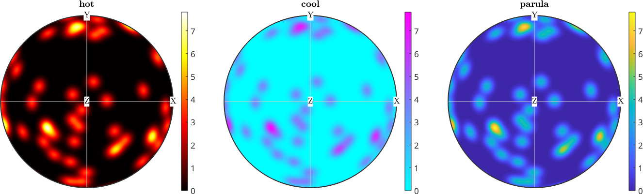
These are three plots of the same random directions, yet each colormap gives a different visual impression. Every panel gets a colour bar of its own, because one bar carries a single colormap and would describe only one of the three axes. That is the cost of using several colour mappings in one figure.
References
- S. R. Midway, Principles of Effective Data Visualization, Patterns 1 (2020), 100141, explains how colour scales support honest comparisons between plots.
Next
Continue with Contour Plots to choose filled or line contours and to apply the levels introduced here.
Citing this page.
This page is part of the documentation of
MTEX, a free and open
source MATLAB toolbox for analyzing and modeling crystallographic textures.
It was written by The MTEX Developers and is published at
https://mtex-toolbox.github.io/ColorMaps.html.
If you use MTEX, or reuse text or figures from this page, in your research,
please cite
F. Bachmann, R. Hielscher, H. Schaeben: Texture Analysis with MTEX - Free and Open Source Software Toolbox, Solid State Phenomena 160 (2010), 63-68. 10.4028/www.scientific.net/SSP.160.63
BibTeX
@article{bachmann2010mtex,
  author  = {F. Bachmann and R. Hielscher and H. Schaeben},
  title   = {Texture Analysis with MTEX - Free and Open Source Software Toolbox},
  journal = {Solid State Phenomena},
  volume  = {160},
  pages   = {63-68},
  year    = {2010},
  doi     = {10.4028/www.scientific.net/SSP.160.63},
  url     = {https://doi.org/10.4028/www.scientific.net/SSP.160.63}
}
Other papers describing specific MTEX methods are listed under Publications — please cite the one that best fits your application. The MTEX source code is licensed under the GNU General Public License v2.0; the text and figures of this documentation are licensed under CC BY 4.0, which permits reuse — including by automated systems — provided The MTEX Developers and this page are credited.