
Rolling, drawing and recrystallisation produce the same few orientations again and again. These ideal orientations have names such as Cube, Goss, Brass and Copper. Naming the dominant components describes a texture in one sentence. MTEX provides them so that measured orientations can be compared with the conventional ideals.
This page assumes the orientation defined in Defining Orientations. It also uses the plane and direction notation from Miller Indices. Symmetry explains why one physical component has several equivalent coordinate descriptions.
Predefined Components and Their Frame
The complete set of predefined orientation constructors is
- Cube, CubeND22, CubeND45, CubeRD
- Goss, invGoss
- Copper, Copper2
- SR, SR2, SR3, SR4
- Brass, Brass2
- PLage, PLage2, QLage, QLage2, QLage3, QLage4
These names are conventions for cubic rolling and recrystallisation textures. Their Euler angles require the same Bunge convention and frames. See MTEX vs. Bunge Convention. The numbered constructors retain variants that may be distinct under weak specimen symmetry. With orthorhombic specimen symmetry, several are equivalent.
A reference frame is the coordinate system in which data are expressed. Here the specimen frame is the rolling frame. Specimen X is the rolling direction (RD), and Y is the transverse direction (TD). Specimen Z is the normal direction (ND). The plotting convention below draws RD north and TD west. Consequently, ND points out of the page.
plottingConvention.default('y←↑x');

% use cubic crystal symmetry and orthorhombic specimen symmetry
cs = crystalSymmetry('m-3m');
ss = specimenSymmetry('orthorhombic');
ss.frame = specimenFrame.rolling;
A Representative Selection
The following subset contains common ideal components and several rotated Cube components.
components = [...
  orientation.goss(cs,ss),...
  orientation.brass(cs,ss),...
  orientation.cube(cs,ss),...
  orientation.cubeND22(cs,ss),...
  orientation.cubeND45(cs,ss),...
  orientation.cubeRD(cs,ss),...
  orientation.copper(cs,ss),...
  orientation.PLage(cs,ss),...
  orientation.QLage(cs,ss),...
  ];

componentNames = ["Goss","Brass","Cube","CubeND22","CubeND45",...
  "CubeRD","Copper","PLage","QLage"];
Plane and Direction Notation
Each legend entry below is generated in the conventional form \((hkl)[uvw]\). The plane \((hkl)\) faces the sheet normal, and the direction \([uvw]\) points along the rolling direction. Equivalently, the orientation maps the plane normal to ND and the lattice direction to RD. orientation.byMiller uses this argument order.
Matching a Measured Orientation
A component match is an angular comparison, not a comparison of three Euler-angle columns. As a reproducible stand-in for a measurement, make an orientation five degrees from the Copper entry. Then compare it with every component.
measured = orientation.byEuler(Euler(components(7)) + ...
  [5 0 0] * degree,cs,ss);

componentDistance = angle(measured,components) ./ degree;
[bestDifference,bestId] = min(componentDistance);

bestMatch = componentNames(bestId)
bestDifference
bestMatch =
"Copper"
bestDifference =
5.0000The closest entry is Copper at \(5^\circ\). angle uses the attached crystal and specimen symmetries. It therefore compares physical components rather than arbitrary stored representatives. A real analysis must also state the angular tolerance used to call an orientation part of a component.
Three-Dimensional Euler Angle Space
The first view places every component at its three Bunge Euler angles.
close all
for i = 1:length(components)
  plot(components(i),'bunge','MarkerSize',10,...
    'MarkerColor',ind2color(i),...
    'DisplayName',round2Miller(components(i),'LaTex'))
  hold on
end
legend('show','interpreter','LaTeX','location','southoutside',...
  'numColumns',3,'FontSize',1.2*getMTEXpref('FontSize'));
hold off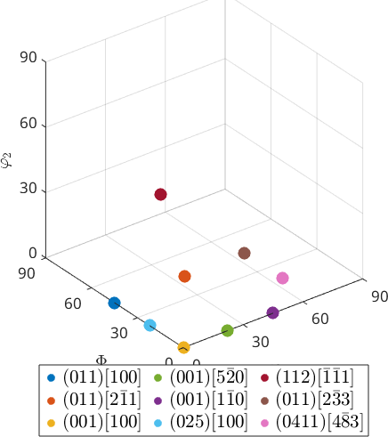
Notice Cube at the zero-angle corner. CubeND22 and CubeND45 move along the \(\varphi_1\) edge, whereas CubeRD moves along the \(\Phi\) edge. This plot is a coordinate chart. Proximity near a chart boundary need not mean a small physical orientation difference.
Two-Dimensional phi2 Sections
The classical paper view uses sections of fixed \(\varphi_2\). This is how rolling components are usually recognized in an ODF. See Euler Angle Sections.
close all
for i = 1:length(components)
  plotSection(components(i),'add2all','MarkerColor',ind2color(i),...
    'DisplayName',round2Miller(components(i),'LaTex'))
end

legend('show','interpreter','LaTeX','location','southeast',...
  'FontSize',1.2*getMTEXpref('FontSize'));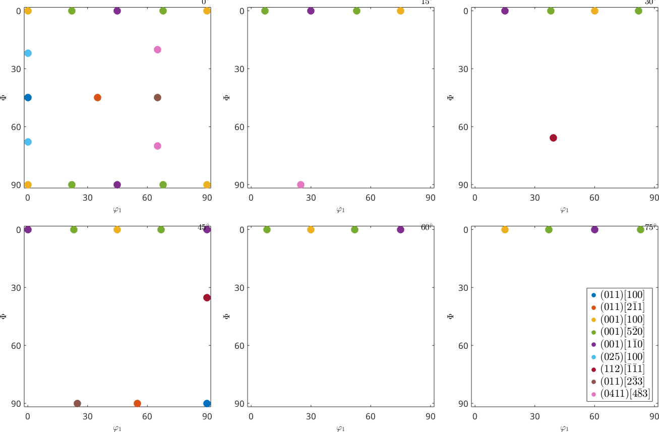
Notice that one colour can occur at several coordinate positions. These are symmetry-equivalent representatives of one component. They are not additional physical components.
Three-Dimensional Axis-Angle Space
Axis-angle space places the same components inside the fundamental region of the cubic-orthorhombic symmetry pair. See Fundamental Region.
close all
for i = 1:length(components)
  hold on
  plot(components(i),'axisAngle','MarkerSize',10,...
    'MarkerColor',ind2color(i),...
    'DisplayName',round2Miller(components(i),'LaTex'))
  axis off
end
legend('show','interpreter','LaTeX','location','southoutside',...
  'numColumns',3,'FontSize',1.2*getMTEXpref('FontSize'));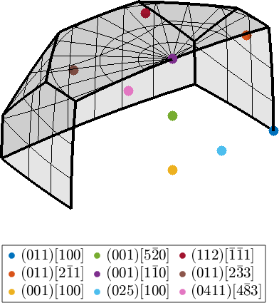
Cube is the identity orientation at zero rotation. Every other marker is one representative chosen from its symmetry class. All nine components therefore fit into the single fundamental region.
Pole Figures
A pole figure shows where each component puts selected families of lattice planes. This is the view against which a measured pole figure is compared.
h = Miller({1,0,0},{1,1,0},{1,1,1},{3,1,1},cs);

close all
for i = 1:length(components)
  plotPDF(components(i),h,'MarkerSize',10,...
    'MarkerColor',ind2color(i),...
    'DisplayName',round2Miller(components(i),'LaTex'))
  hold on
end
hold off

legend('show','interpreter','LaTeX','location','northeast',...
  'numColumns',2,'FontSize',1.2*getMTEXpref('FontSize'));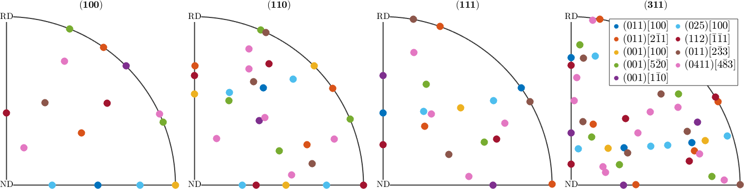
For Goss, the \(\{110\}\) family has a pole in the centre because its \((011)\) plane faces ND. Cube puts \(\{100\}\) poles in the centre and on the RD and TD axes of the rim.
Inverse Pole Figures
Inverse pole figures ask the opposite question: which crystal direction lies along specimen X, Y or Z? In this rolling frame those directions are RD, TD and ND.
r = [vector3d.X,vector3d.Y,vector3d.Z];

close all
for i = 1:length(components)
  plotIPDF(components(i),r,'MarkerSize',(12-i)^1.5,...
    'MarkerColor',ind2color(i),...
    'DisplayName',round2Miller(components(i),'LaTex'))
  hold on
end
hold off

legend('show','interpreter','LaTeX','location','northeast',...
  'numColumns',2,'FontSize',1.2*getMTEXpref('FontSize'));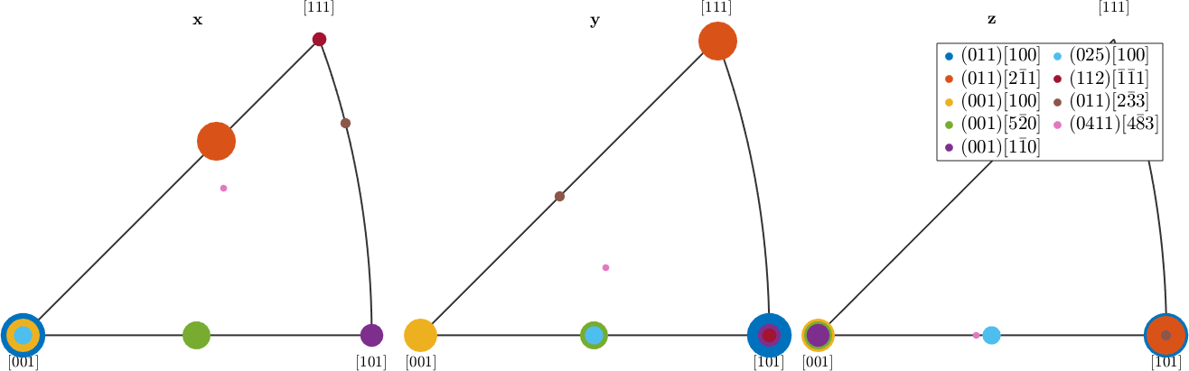
Several components put the same crystal direction along one specimen axis but differ by rotation about it. Their markers coincide in that panel, so the decreasing marker sizes keep all components visible. An inverse pole figure loses the rotation about the plotted direction. Therefore, it cannot identify a full orientation by itself.
From a Component to a Model Texture
A named component is a single ideal orientation. A real texture has a spread around that ideal. Giving the component a halfwidth turns it into a model ODF. This is the quantity fitted against measured data; see Modeling ODFs.
odf = unimodalODF(components(3),'halfwidth',7.5*degree)

plotPDF(odf,h)
hold on
plotPDF(odf,h,'contour','lineColor','k','linewidth',2)
hold off
odf = SO3FunRBF (m3̅m → TD←RD↑ (mmm))
unimodal component
kernel: de la Vallee Poussin, halfwidth 7.5°
center: 1 orientations
Bunge Euler angles in degree
phi1 Phi phi2 weight
0 0 0 1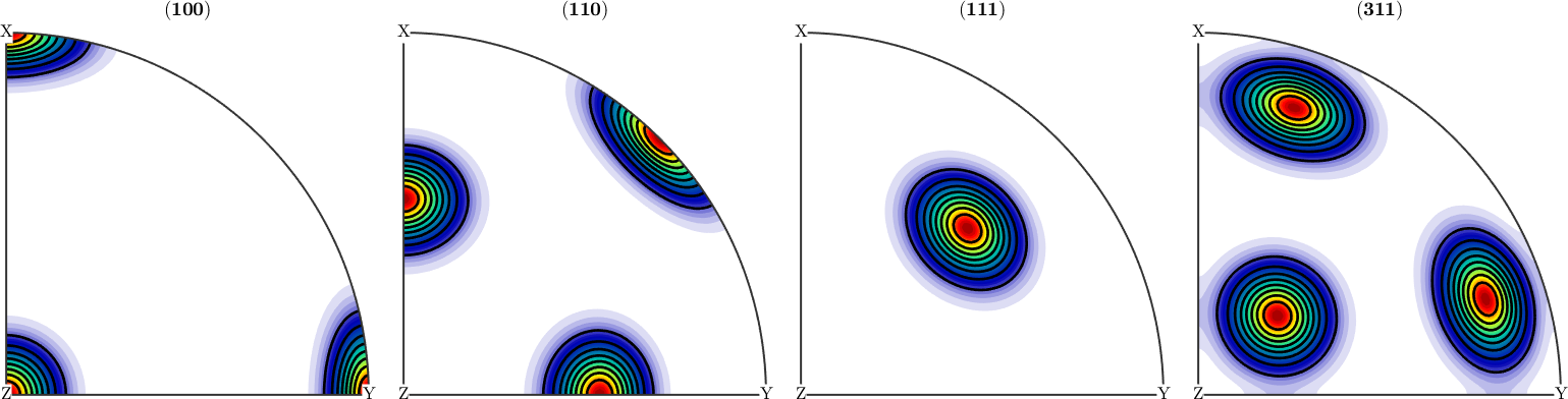
The isolated Cube markers have become density peaks at the same pole positions. At \(7.5^\circ\), the radial kernel falls to half its maximum. This halfwidth is a radius, not a \(15^\circ\) uniform band.
The Model in Inverse Pole Figures
The same spread appears around the Cube directions in the inverse pole figures.
plotIPDF(odf,r)
hold on
plotIPDF(odf,r,'contour','lineColor','k','linewidth',2)
hold off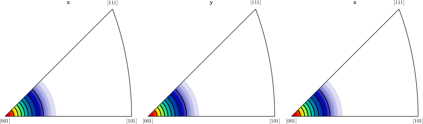
Notice that the peak centres agree with the Cube markers in the earlier inverse pole figures. Only the ideal point has changed into a continuous neighbourhood.
The Model in phi2 Sections
Finally, plot the model in \(\varphi_2\) sections and overlay all nine ideal components to identify the centre used to build it.
plotSection(odf)

hold on
plotSection(odf,'contour','lineColor','k','linewidth',2)

for i = 1:length(components)
  plotSection(components(i),'MarkerSize',10,'filled',...
    'DisplayName',round2Miller(components(i),'LaTex'))
end

hold off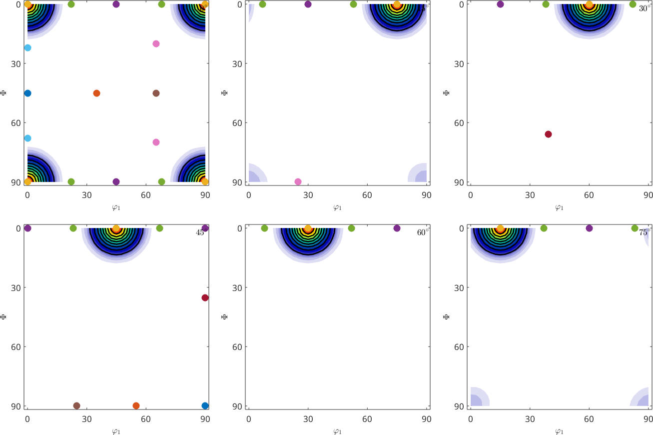
The density maximum sits on Cube. The other component markers remain isolated reference points and do not contribute to this model ODF.
References
- H.-J. Bunge, Texture Analysis in Materials Science: Mathematical Methods, Butterworths, 1982. It establishes the Euler-angle and ODF conventions used in texture analysis.
- U. F. Kocks, C. N. Tomé and H.-R. Wenk, Texture and Anisotropy, Cambridge University Press, 2nd ed., 2000. It connects named components with processing and material anisotropy.
- O. Engler and V. Randle, Introduction to Texture Analysis, CRC Press, 2nd ed., 2010. It gives a practical treatment of macrotexture, microtexture and orientation mapping.
- L. A. I. Kestens and H. Pirgazi, Texture formation in metal alloys with cubic crystal structures, Materials Science and Technology 32 (2016). It reviews the common rolling components of cubic alloys.
Next
MTEX vs. Bunge Convention explains which published Euler-angle triplets can be copied directly. Pole figures are developed in Pole Figures. The reverse view is Inverse Pole Figures.
Fibres of Orientations follows the named fibre components through orientation space. Modeling ODFs develops the model textures introduced above.
Citing this page.
This page is part of the documentation of
MTEX, a free and open
source MATLAB toolbox for analyzing and modeling crystallographic textures.
It was written by The MTEX Developers and is published at
https://mtex-toolbox.github.io/OrientationStandard.html.
If you use MTEX, or reuse text or figures from this page, in your research,
please cite
F. Bachmann, R. Hielscher, H. Schaeben: Texture Analysis with MTEX - Free and Open Source Software Toolbox, Solid State Phenomena 160 (2010), 63-68. 10.4028/www.scientific.net/SSP.160.63
BibTeX
@article{bachmann2010mtex,
  author  = {F. Bachmann and R. Hielscher and H. Schaeben},
  title   = {Texture Analysis with MTEX - Free and Open Source Software Toolbox},
  journal = {Solid State Phenomena},
  volume  = {160},
  pages   = {63-68},
  year    = {2010},
  doi     = {10.4028/www.scientific.net/SSP.160.63},
  url     = {https://doi.org/10.4028/www.scientific.net/SSP.160.63}
}
Other papers describing specific MTEX methods are listed under Publications — please cite the one that best fits your application. The MTEX source code is licensed under the GNU General Public License v2.0; the text and figures of this documentation are licensed under CC BY 4.0, which permits reuse — including by automated systems — provided The MTEX Developers and this page are credited.