
An EBSD map couples every measured orientation to a position. This page deliberately discards those positions and asks a texture question: does this rock have a fibre texture? The example begins with a plausible but incomplete answer, then tests it in all three dimensions of orientation space.
The page assumes phase selection from Select EBSD Data and the pole and inverse pole figures introduced in Orientation Plots. A reference frame is the coordinate system in which the data are expressed. Check it as described in Reference Frame before interpreting any specimen direction.
A plotting convention states how that frame is laid out on screen. The convention below draws specimen Y upward and specimen X to the right. It changes only the screen layout, not the measured orientations.
plottingConvention.default('y↑→x');
mtexdata forsterite silent

plot(ebsd)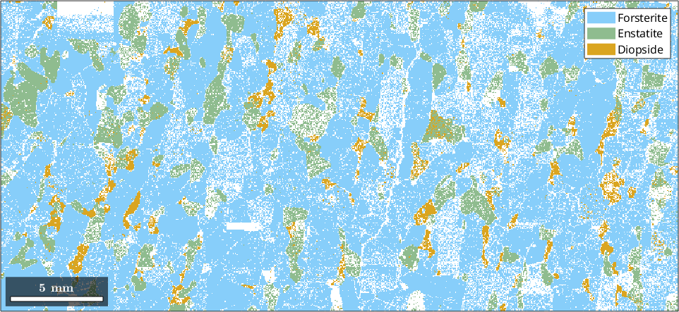
The phase map establishes the spatial context: forsterite occupies most of the indexed area and occurs in a modest number of large grains. No position is used below. This dense scan therefore contributes many similar orientations from each large grain, a weighting issue revisited at the end of the page. For analysis that retains position, see Profiles.
A first look at the pole figures
A pole figure fixes a crystal direction and shows where it points in the specimen. Plot the density of the three principal forsterite poles.
% crystal symmetry of the forsterite phase
cs = ebsd('Forsterite').CS;
h = [Miller(1,0,0,cs),Miller(0,1,0,cs),Miller(0,0,1,cs)];
plotPDF(ebsd('Forsterite').orientations,h,'antipodal','smooth')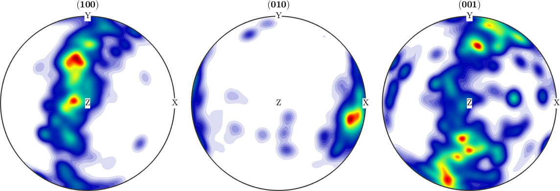
The \((100)\) density forms a girdle, a band along a great circle, rather than one compact spot. A fibre texture can produce this pattern: all crystals share one direction and are otherwise free to turn about it. A single pole figure discards that free rotation, however, so the girdle is a hypothesis rather than proof of a fibre texture.
Finding the specimen axis
If the \((100)\) poles lie on a great circle, there is a specimen axis orthogonal to all of them. perp finds the axis that is closest to being orthogonal to the measured poles in a least-squares sense.
% orientations of the forsterite phase
ori = ebsd('Forsterite').orientations;

% specimen vectors in the 100 pole figure
r = ori * Miller(1,0,0,ori.CS);

% specimen axis best orthogonal to the pole vectors
rOrth = perp(r)

plot(rOrth,'add2all','Marker','square','markerColor','DarkRed')
rOrth = vector3d (y↑→x)
antipodal: true
x y z
0.944 -0.19 0.269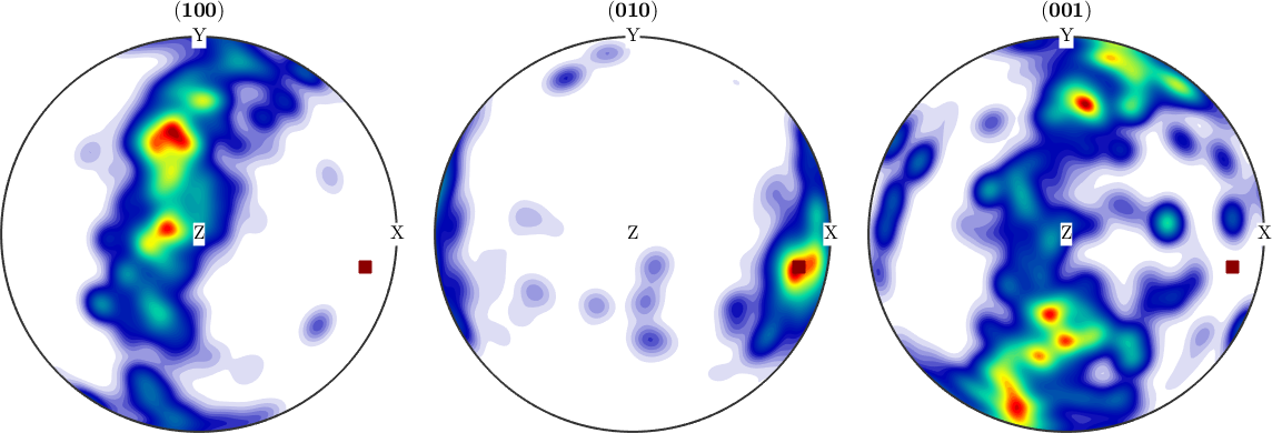
The displayed result is an antipodal axis: either sign is the same normal to the girdle plane. The square marks it in all three pole figures. It lies away from the \((100)\) density, as the pole of a great circle must, and near the densest part of the \((010)\) figure. The second observation is a clue to the crystal direction of the candidate fibre.
Draw the edge of the band whose points lie within 10° of the great circle. Its opening angle about rOrth is therefore 80°.
nextAxis(1)
circle(rOrth,80*degree,'lineColor','darkred','lineWidth',5,...
  'EdgeAlpha',0.5)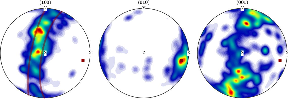
Count the measurements inside that band. Because rOrth is antipodal, its angular distance ranges from 0° to 90°.
girdleFraction = 100 * sum(angle(r,rOrth) > 80*degree) / length(ori)girdleFraction =
61.7854Nearly 62% of the measurements have their crystal \(a\) axis within 10° of the great circle. This first, one-direction test looks convincing, but it has not yet tested a complete orientation.
Which crystal direction is the fibre axis
A fibre needs a crystal direction as well as a specimen direction. It is the set of orientations that map one fixed crystal direction onto one fixed specimen direction while leaving rotation about that direction free. Fibres of Orientations develops this geometry.
The inverse pole figure of rOrth asks which crystal direction points along that specimen axis.
plotIPDF(ori,rOrth,'smooth')
mtexColorbar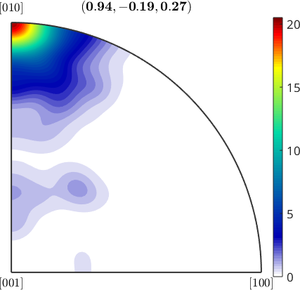
The density piles up near \((010)\), so the candidate fibre maps the crystal \(b\) axis onto rOrth.
% candidate fibre through orientation space
f = fibre(Miller(0,1,0,cs),rOrth);

% percentage of measurements within 10 degrees of the fibre
fibreFraction = 100 * volume(ori,f,10*degree)
fibreFraction =
27.9806The 28% is less than half of the 62%, and the difference is the point. Lying in the girdle says only that the \(a\) axis avoids rOrth. Lying near the fibre says in addition that the \(b\) axis points towards rOrth. Every orientation on this fibre lies in the girdle, but most orientations in the girdle do not lie on the fibre.
The exact fibre is a one-dimensional curve and has zero volume in orientation space. volume reports the fraction of measured orientations inside the specified 10° tube around that curve. The radius is therefore part of the result. For an unknown direction pair, fibre.fit can search for a candidate, but the same geometrical and sampling checks are still required.
What the ODF says
A true fibre texture has constant density along its fibre. An orientation distribution function (ODF) estimates density throughout orientation space. Estimate it from the measurements and follow it along f. ODF Estimation explains the kernel and its halfwidth.
odf = calcDensity(ori,'silent');

% plot the ODF along the candidate fibre
plot(odf,f,'lineWidth',2,'figSize','small')
ylim([0,26])

% evaluate the same fibre points to report the plotted range
fibreOri = orientation(f,odf.CS,odf.SS);
fibreDensity = eval(odf,fibreOri);
densityRange = [min(fibreDensity),max(fibreDensity)]

% count peaks that rise by at least 1 mrd
peakCountPerHalfTurn = nnz(islocalmax(fibreDensity,...
  'MinProminence',1)) / 2
densityRange =
5.5218 19.6383
peakCountPerHalfTurn =
3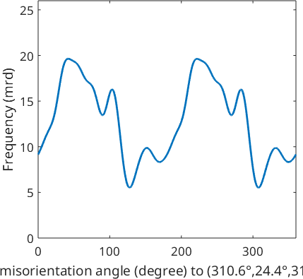
A fibre texture would give a flat line. This one swings between 5.5 and 19.6 multiples of a uniform distribution, a factor of three and a half. Three peaks rise by at least 1 mrd in every half turn. Together with the 28% fibre fraction, this settles the question: the map does not show a fibre texture. It contains a few strong components that share a plane.
Why the peaks are there
Plot the complete density in sections through orientation space to see where the variation along the fibre comes from.
plot(odf,'sigma')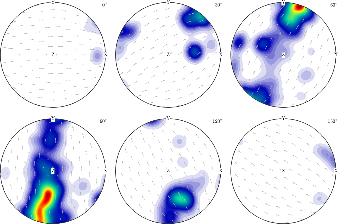
The sections contain large isolated spots rather than a continuous ridge. This is what a densely sampled map with few grains produces: each grain contributes thousands of nearly identical orientations, so one large grain can become one ODF peak.
Here every measurement has equal weight. On a regular scan that is approximately an area-weighted texture, not a count in which every grain has one vote. The estimate describes the grains in the measured area and need not represent the rock from which that small area was taken. For texture analysis, a coarser step over a larger area would have been the better measurement. Reconstructing grains also makes it possible to compare area-weighted and equal-grain orientation distributions.
Further reading
- H.-J. Bunge, Texture Analysis in Materials Science: Mathematical Methods, Butterworths, English ed., 1982, develops pole figures, fibre textures, and orientation distribution functions.
- J. Galán López and L. A. I. Kestens, A multivariate grain size and orientation distribution function: derivation from electron backscatter diffraction data and applications, Journal of Applied Crystallography 54 (2021), 148-162, distinguishes grain frequency from volume-weighted texture and treats correlations between grain size and orientation.
- ISO 24173:2024, Microbeam analysis - Guidelines for orientation measurement using electron backscatter diffraction, gives guidance for reliable and reproducible EBSD orientation measurements.
Next
Grain Reconstruction restores spatial connectivity and provides one mean orientation and area per grain. ODF Estimation then develops pixel weighting, grain weighting, and kernel choice. ODF Analysis continues with quantitative texture analysis in orientation space.
Citing this page.
This page is part of the documentation of
MTEX, a free and open
source MATLAB toolbox for analyzing and modeling crystallographic textures.
It was written by The MTEX Developers and is published at
https://mtex-toolbox.github.io/EBSDOrientationAnalysis.html.
If you use MTEX, or reuse text or figures from this page, in your research,
please cite
F. Bachmann, R. Hielscher, H. Schaeben: Texture Analysis with MTEX - Free and Open Source Software Toolbox, Solid State Phenomena 160 (2010), 63-68. 10.4028/www.scientific.net/SSP.160.63
BibTeX
@article{bachmann2010mtex,
  author  = {F. Bachmann and R. Hielscher and H. Schaeben},
  title   = {Texture Analysis with MTEX - Free and Open Source Software Toolbox},
  journal = {Solid State Phenomena},
  volume  = {160},
  pages   = {63-68},
  year    = {2010},
  doi     = {10.4028/www.scientific.net/SSP.160.63},
  url     = {https://doi.org/10.4028/www.scientific.net/SSP.160.63}
}
Other papers describing specific MTEX methods are listed under Publications — please cite the one that best fits your application. The MTEX source code is licensed under the GNU General Public License v2.0; the text and figures of this documentation are licensed under CC BY 4.0, which permits reuse — including by automated systems — provided The MTEX Developers and this page are credited.