A grain is a phase-homogeneous, spatially connected region of EBSD pixels produced by segmentation. A subgrain boundary lies inside such a grain. A low-angle boundary is instead defined by its misorientation angle. The two ideas usually overlap, but they are not synonyms.
Low-angle boundaries can be described as arrays of dislocations. Their energy and structure change with misorientation until the dislocation cores begin to overlap. The conventional transition to high-angle boundaries lies between about 5 and 15 degrees, depending on the material. Above it, the energy depends less strongly on angle apart from special orientations with lower energy.
Deformation stores dislocations inside grains. During recovery, some of them organize into walls that divide a grain into subgrains. This page shows how MTEX records, draws, and measures those walls.
The page assumes that the EBSD map has already been segmented in principle. See Grain Reconstruction for that step. Grain Boundary Properties introduces boundary segments and connected components. See Misorientations at Grain Boundaries for the distinction between crystal-frame and specimen-frame axes.
close all;

% use the rolling-direction frame carried by the ferrite specimen
plottingConvention.default('y↑→x');

% load a deformed ferrite map
mtexdata ferrite silent
Reconstruct grains and their internal boundaries
A single segmentation threshold has to choose between grain scale and subgrain scale. At 10 degrees the low-angle walls are missed. At 1 degree the same walls divide the map into many separate grains.
calcGrains accepts both thresholds at once. The first value separates grains, while the second records boundaries whose two pixels remain in the same grain as innerBoundary.
highAngle = 10*degree;
lowAngle = 1*degree;
[grains,ebsd] = calcGrains(ebsd,'angle',[highAngle lowAngle],...
  'minPixel',5);

% remove the pixel staircase before measuring boundary lengths
grains = smoothBoundary(grains,5);
What innerBoundary means
An inner boundary is a topological result, not a second angle filter. MTEX marks a pixel pair as a boundary and then reconstructs connected grains. Two pixels can remain in the same grain through another path even when their direct misorientation exceeds the high-angle threshold.
The strict low-angle selection therefore applies the angle criterion explicitly. The printed table keeps the distinction visible.
innerAngle = grains.innerBoundary.misorientation.angle;
isLowAngle = innerAngle <= highAngle;
subGB = grains.innerBoundary(isLowAngle);

boundaryCounts = table(length(grains.boundary),...
  length(grains.innerBoundary),length(subGB),nnz(~isLowAngle),...
  'VariableNames',{'grainBoundarySegments','innerBoundarySegments',...
  'strictLowAngleSegments','innerSegmentsAboveHighAngle'})
boundaryCounts =
1×4 table
grainBoundarySegments innerBoundarySegments strictLowAngleSegments innerSegmentsAboveHighAngle
_____________________ _____________________ ______________________ ___________________________
15738 31037 30577 460Draw the subgrain-boundary network
The table reports 15,738 boundary segments between grains and 31,037 inner boundary segments. Of the latter, 30,577 satisfy the strict low-angle selection and 460 exceed 10 degrees for the topological reason above. Default boundary smoothing simplifies and resamples the network, so these are post-smoothing segment counts rather than physical lengths.
Drawing the inner boundaries with a transparency that follows their misorientation angle keeps the strongest walls visible and lets the weakest fade out.
Compute the IPF colours explicitly so that the map does not print an unrelated automatic-colour-key message.
ebsdIndexed = ebsd('indexed');
ipfKey = ipfColorKey(ebsdIndexed.CS);
ipfColor = ipfKey.orientation2color(ebsdIndexed.orientations);

% make stronger low-angle boundaries more opaque
alpha = min(subGB.misorientation.angle ./ (5*degree),1);

plot(ebsdIndexed,ipfColor,'faceAlpha',0.5,'figSize','large')
hold on
plot(grains.boundary,'lineWidth',2)
plot(subGB,'lineWidth',1.5,'edgeAlpha',alpha,'lineColor','blue')
hold off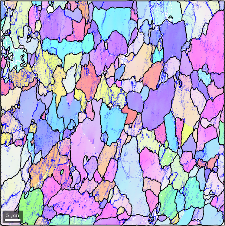
Black lines separate grains. Blue lines are the strictly selected low-angle boundaries within them. Strong walls cross some grain interiors, while other grains contain almost none. The contrast may reflect heterogeneous deformation, but short isolated lines may also be noise.
Normalize the amount within each grain
subBoundarySize counts inner-boundary segments belonging to each grain. Its optional logical selection keeps only the strict low-angle population. Dividing by the number of pixels removes most of the effect of grain size within this one map.
segmentDensity = grains.subBoundarySize(isLowAngle) ./ grains.numPixel;
plot(grains,segmentDensity)
mtexColorbar('title','segments per pixel')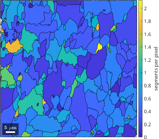
Grains crossed by many blue walls have the largest segment-per-pixel values. This ratio is useful within one regular grid, but it changes with pixel spacing and should not be compared between acquisitions.
The physical-unit alternative uses subBoundaryLength. Dividing the selected length by area gives boundary length per area, here in inverse micrometres.
lengthDensity = grains.subBoundaryLength(isLowAngle) ./ grains.area;
plot(grains,lengthDensity)
mtexColorbar('title','boundary length / area (1/µm)')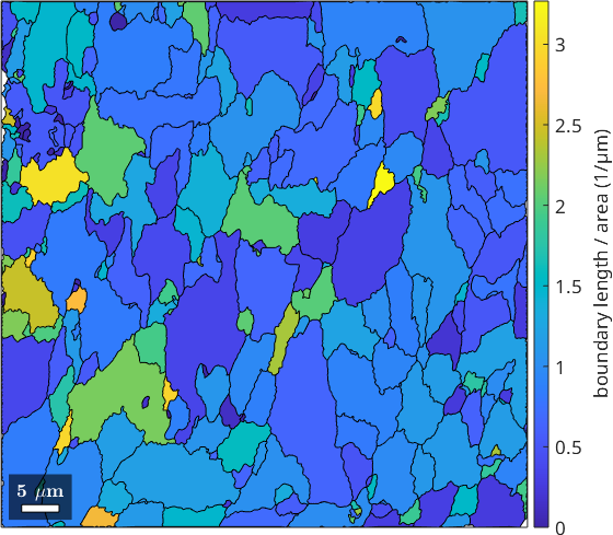
The length-density map singles out the same grains as the count-density map. The two measures are nearly proportional on this regular grid. Length per area is the quantity to report because it has physical units. It removes the direct segment-count dependence, but detection still depends on step size, angular precision, thresholds, and smoothing.
Misorientation axes of the low-angle boundaries
The misorientation axis describes the rotation across a wall. Its relation to the boundary plane distinguishes tilt, twist, and mixed character. It is not generally the line direction of every dislocation in the wall.
The density estimate below is weighted by segment length, so resampling a long wall into more segments does not give it extra influence. A 5 degree kernel smooths the discrete axes into a distribution.
axisDensity = calcDensity(subGB.misorientation.axis,...
  'weights',subGB.segLength,'halfwidth',5*degree);
plot(axisDensity,'fundamentalRegion','contourf','figSize','small')
mtexColorbar('title','mrd')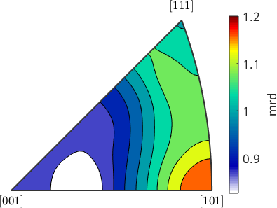
The colour scale spans about 0.83 to 1.20 multiples of random distribution (mrd), where 1 is uniform. This ferrite analysis therefore resolves no strong preferred crystal-frame rotation axis. Compare the two clear maxima in the forsterite example of Tilt and Twist Boundaries. That page also computes the axes in specimen coordinates and compares them with traces.
A nearly uniform result is not proof that the physical axes are random. Most boundaries here are only a few degrees across, where small EBSD orientation errors can cause large axis errors. Interpret low-angle axes as a population and check the acquisition precision.
Networks and isolated segments
A wall crossing a grain and a few isolated segments above 1 degree have different physical meanings. componentSize gives each segment the number of segments in its connected group. Here a dataset-specific cutoff of 50 segments separates larger networks from shorter features.
isNetwork = subGB.componentSize > 50;
allInnerIsNetwork = grains.innerBoundary.componentSize > 50;
fprintf(['Segments in components above 50: %.1f%% of the strict ',...
  'low-angle set; %.1f%% of all inner boundaries\n'],...
  100*mean(isNetwork),100*mean(allInnerIsNetwork));

plot(ebsdIndexed,ipfColor,'faceAlpha',0.5,'figSize','large')
hold on
plot(grains.boundary,'lineWidth',2)
plot(subGB(isNetwork),'lineWidth',1.5,...
  'edgeAlpha',alpha(isNetwork),'lineColor','blue')
plot(subGB(~isNetwork),'lineWidth',1.5,...
  'edgeAlpha',alpha(~isNetwork),'lineColor','red')
hold off
Segments in components above 50: 29.1% of the strict low-angle set; 30.8% of all inner boundaries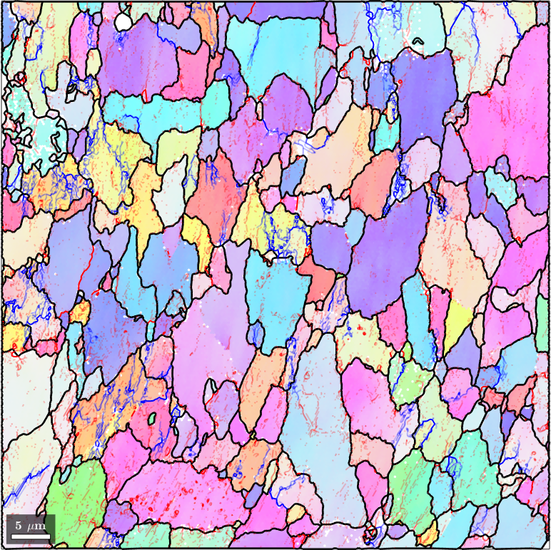
Blue marks continuous structures, often running across a grain and meeting its boundary at both ends. Red marks short components. Many are likely orientation noise crossing the 1 degree threshold, although a short component is not proof of noise.
The strict selection puts 29.1 percent of its segments in components above 50. Counting every inner boundary gives 30.8 percent, or about the 31 percent obtained without the explicit angle filter. Both populations are counted by the density maps above, and that is worth remembering before reading much into a small difference between two grains. The 50-segment cutoff itself changes with resampling and step size, so choose it again for a new map.
References
- F. Bachmann, R. Hielscher, and H. Schaeben, Grain Detection from 2d and 3d EBSD Data---Specification of the MTEX Algorithm, Ultramicroscopy 111 (2011), 1720--1733. This paper defines the spatial reconstruction on which
calcGrainsis based. - W. T. Read and W. Shockley, Dislocation Models of Crystal Grain Boundaries, Physical Review 78 (1950), 275--289. This is the classical dislocation model for low-angle boundary energy.
- F. J. Humphreys and M. Hatherly, Recrystallization and Related Annealing Phenomena, 2nd ed., Pergamon, 2004. Chapters on the deformed state and recovery place subgrains in their microstructural context.
- D. J. Prior, Problems in Determining the Misorientation Axes, for Small Angular Misorientations, Using EBSD, Journal of Microscopy 195 (1999), 217--225. This paper quantifies the loss of axis precision at small angles.
- J. Wheeler et al., From Geometry to Dynamics of Microstructure: Using Boundary Lengths to Quantify Boundary Misorientations and Anisotropy, Tectonophysics 376 (2003), 19--35. It motivates length-weighted boundary statistics.
- S. Demouchy, Defects in Olivine, European Journal of Mineralogy 33 (2021), 249--282. Section 5.2.1 and Figure 8 review low-angle walls and illustrate tilt and twist boundaries.
Next
Continue with Tilt and Twist Boundaries to compare the misorientation axis with the boundary trace. For deformation measured at every EBSD point rather than only at detected walls, see Kernel Average Misorientation and Grain Reference Orientation Deviation.
Citing this page.
This page is part of the documentation of
MTEX, a free and open
source MATLAB toolbox for analyzing and modeling crystallographic textures.
It was written by The MTEX Developers and is published at
https://mtex-toolbox.github.io/SubGrainBoundaries.html.
If you use MTEX, or reuse text or figures from this page, in your research,
please cite
F. Bachmann, R. Hielscher, H. Schaeben: Texture Analysis with MTEX - Free and Open Source Software Toolbox, Solid State Phenomena 160 (2010), 63-68. 10.4028/www.scientific.net/SSP.160.63
BibTeX
@article{bachmann2010mtex,
  author  = {F. Bachmann and R. Hielscher and H. Schaeben},
  title   = {Texture Analysis with MTEX - Free and Open Source Software Toolbox},
  journal = {Solid State Phenomena},
  volume  = {160},
  pages   = {63-68},
  year    = {2010},
  doi     = {10.4028/www.scientific.net/SSP.160.63},
  url     = {https://doi.org/10.4028/www.scientific.net/SSP.160.63}
}
Other papers describing specific MTEX methods are listed under Publications — please cite the one that best fits your application. The MTEX source code is licensed under the GNU General Public License v2.0; the text and figures of this documentation are licensed under CC BY 4.0, which permits reuse — including by automated systems — provided The MTEX Developers and this page are credited.