
Density estimation turns a finite sample into a continuous function. In texture analysis, the samples may be EBSD orientations, grain mean orientations, misorientation axes, or simulated orientations.
Keep three parts of the calculation distinct:
- input: samples \(x_n\), possibly with statistical weights;
- assumption: nearby samples belong to a smoothly varying density;
- result: an estimate \(f_N\) of an unknown density \(f\).
Pole-figure intensities are different input. They are sampled values of a projected pole density rather than random orientations. Recovering an ODF from them is an inverse problem, not the kernel estimate described here.
The worked sequence starts with real numbers. It then applies the same construction to directions and orientations.
plottingConvention.default('y↑→x');Begin with a finite sample
Use a mixture of two Gaussian densities as a known reference. The second argument of Gaussian is a width parameter \(\delta\). The profile is \(\exp(-(x-m)^2/\delta^2)\), so \(\delta\) is the standard deviation times \(\sqrt{2}\).
f = @(x) (Gaussian(0.2,0.05,x) + Gaussian(0.5,0.2,x))/2;
x = linspace(0,1,1000);

% draw a sample from the density on [0,1]
N = 20;
xN = discreteSample(f,N,'range',[0,1]);

plot(x,f(x),'LineWidth',2);
hold on;
plot(xN,zeros(size(xN)),'o','LineWidth',2,...
  'MarkerEdgeColor','r');
hold off;
xlabel('x');
ylabel('density');
legend('true density','sample');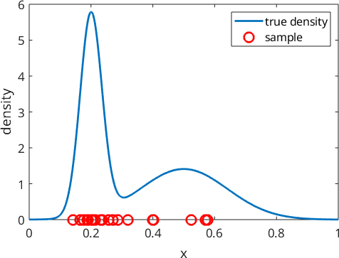
The blue curve has a narrow mode near 0.2 and a broad mode near 0.5. More red samples occur where that curve is high. With only 20 samples, random gaps and clusters are still prominent.
A histogram depends on its bins
A histogram is the simplest density estimate. The 'pdf' normalization puts the bar areas on the same scale as the reference density.
histogram(xN,10,'Normalization','pdf');
hold on;
plot(x,f(x),'LineWidth',2);
plot(xN,zeros(size(xN)),'o','LineWidth',2,...
  'MarkerEdgeColor','r');
hold off;
xlabel('x');
ylabel('density');
legend('histogram','true density','sample');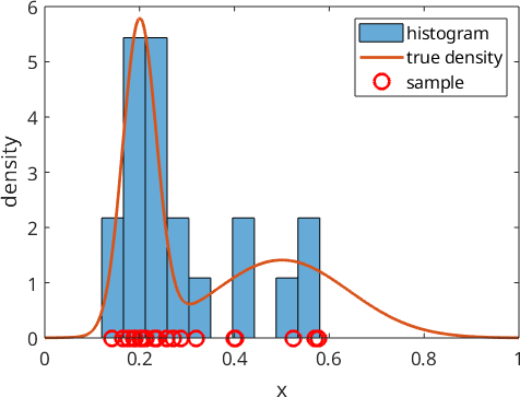
The estimate is piecewise constant, and changing the bin edges changes its steps. The bars hint at two modes, but they do not follow either mode smoothly. Kernel density estimation removes the bin edges.
Replace each sample by a kernel
A kernel is a small density profile placed at one observation. Start with a Gaussian of mean 0 and width 0.05.
psi = Gaussian(0,0.05);

plot(xN,zeros(size(xN)),'o','LineWidth',2,...
  'MarkerEdgeColor','r');
hold on;
for n = 1:N
  plot(x,psi(x-xN(n)),'k');
end
hold off;
xlabel('x');
ylabel('kernel contribution');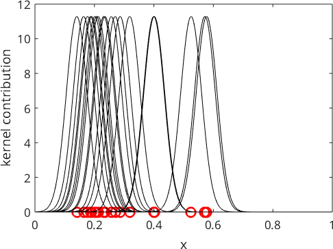
Every black curve has the same shape and total mass. Only its centre changes. Their mean is the kernel density estimate.
fN = @(x) mean(psi(x-xN),1);

plot(x,f(x),'LineWidth',3,'Color',ind2color(1));
hold on;
plot(x,fN(x),'LineWidth',3,'Color',ind2color(2));
hold off;
xlabel('x');
ylabel('density');
legend('true density','kernel estimate');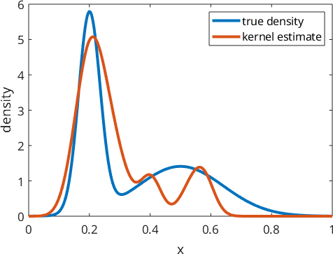
The estimate is smooth, but it is not the true function. Its small peaks record the finite sample as well as the two features of the source.
Kernel width decides which detail survives
Repeat the estimate with widths 0.01, 0.05, and 0.25.
delta = [0.01 0.05 0.25];

plot(x,f(x),'LineWidth',3);
hold on;
for d = delta
  psiTrial = Gaussian(0,d);
  fTrial = @(x) mean(psiTrial(x-xN),1);
  plot(x,fTrial(x),'LineWidth',2);
end
hold off;
xlabel('x');
ylabel('density');
legend('\(f\)','\(f_{0.01}\)','\(f_{0.05}\)','\(f_{0.25}\)',...
  'Interpreter','latex');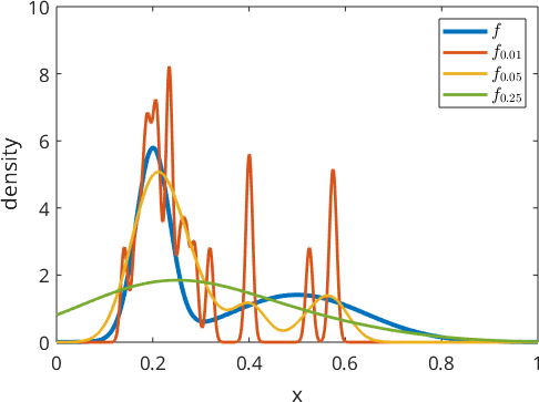
The 0.01 estimate retains a noisy peak for almost every observation. The 0.25 estimate merges the two source modes and lowers their peaks. The middle curve balances sample-scale variation against lost structure. This is the bias--variance trade-off behind kernel selection.
For one-dimensional real data, calcDensity selects a smoothing width automatically.
[fAuto,autoBandwidth] = calcDensity(xN,'range',[0;1]);
autoBandwidth

plot(x,f(x),'LineWidth',2);
hold on;
plot(x,fAuto(x),'LineWidth',2);
hold off;
xlabel('x');
ylabel('density');
legend('true density','automatic estimate');
t_star =
0.0023
autoBandwidth =
0.0484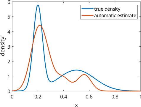
The automatic estimate smooths the sample without reproducing every observation as a separate peak. Its left mode sits on the true one at \(x = 0.2\). Its right mode sits near \(x = 0.67\), well to the right of the true mode at \(x = 0.5\), and it is the taller of the two.
The bandwidth is estimated from the same twenty samples, and twenty samples do not locate the broad component of the mixture. Read the estimate as one draw rather than as the density itself.
For one-dimensional data, the 'bandwidth' option fixes the smoothing parameter instead.
fFixed = calcDensity(xN,'range',[0;1],'bandwidth',0.004);Optimal Kernel Selection explains why no single width is best for every sample.
The construction also works in several dimensions
Draw 100 independent pairs whose x and y coordinates follow the same mixture. A row of [xN,yN] is now one two-dimensional observation.
N = 100;
xN = discreteSample(f,N,'range',[0,1]);
yN = discreteSample(f,N,'range',[0,1]);

scatter(xN,yN,'o','LineWidth',2,'MarkerEdgeColor','r');
axis equal tight;
xlim([0,1]);
ylim([0,1]);
box on;
xlabel('x');
ylabel('y');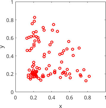
The sample cloud is concentrated near combinations of the two one-dimensional modes. The empty space between points is not assigned zero density; the next step estimates it from neighbouring observations.
For \(d\)-dimensional data, the range has one column per coordinate. The first row contains the minima, and the second contains the maxima.
fN = calcDensity([xN,yN],'range',[0 0;1 1]);

[xGrid,yGrid] = ndgrid(linspace(0,1));
contourf(xGrid,yGrid,fN(xGrid,yGrid),'LevelStep',2);
mtexColorMap LaboTeX;
shading interp;
axis equal tight;
hold on;
scatter(xN,yN,'.','r');
hold off;
xlabel('x');
ylabel('y');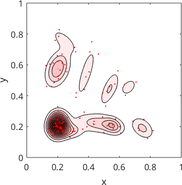
The estimate is positive everywhere, but most of the square carries very little of it. The LaboTeX colour map starts at white, and most of the grid falls in the lowest contour band, so the field reads as a few pink islands on a white ground.
White here means density below the first contour, not zero. The islands sit at the four combinations of the two one-dimensional modes. The pair of narrow modes near \(x = 0.2\), \(y = 0.2\) is by far the densest, and the pair of broad modes near \(x = 0.5\), \(y = 0.5\) is the faintest.
Directions need kernels on the sphere
A directional kernel uses angular distance on the sphere rather than ordinary distance on a line. As a crystallographic example, estimate the distribution of misorientation axes along one phase boundary population. A misorientation axis is the direction about which one crystal must be rotated to match the other.
mtexdata forsterite silent
grains = calcGrains(ebsd);

% Select boundaries between forsterite and enstatite grains.
gB = grains.boundary('Forsterite','Enstatite');
misAxes = gB.misorientation.axis;

plot(misAxes,'fundamentalRegion','MarkerFaceAlpha',0.1);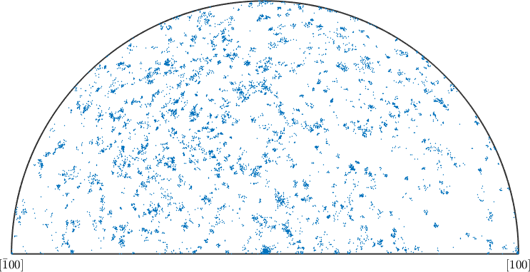
Symmetry maps equivalent axes into the same fundamental region. The points cluster instead of covering that region uniformly, so a density can summarize their preferred directions.
axisDensity = calcDensity(misAxes);

contourf(axisDensity);
mtexColorMap LaboTeX;
mtexColorbar;
hold on;
plot(misAxes,'MarkerEdgeAlpha',0.25,...
  'MarkerFaceColor','none','MarkerEdgeColor','k');
hold off;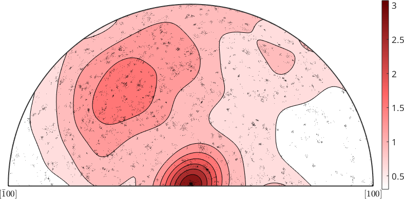
The contours join nearby black observations into broad maxima. The result is an S2FunHarmonicSym and supports the operations in Spherical Function Operations.
Repeat the calculation with a 5 degree halfwidth.
axisDensity5 = calcDensity(misAxes,'halfwidth',5*degree);

contourf(axisDensity5);
mtexColorMap LaboTeX;
mtexColorbar;
hold on;
plot(misAxes,'MarkerEdgeAlpha',0.25,...
  'MarkerFaceColor','none','MarkerEdgeColor','k');
hold off;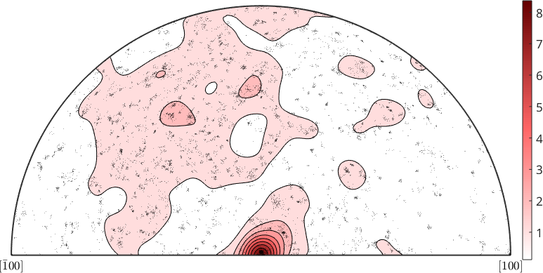
The smaller halfwidth keeps narrower, more fragmented maxima around the observations. That extra detail is not automatically extra information; it may be sampling variation.
Orientations need kernels in orientation space
Applying the construction to orientations produces an orientation distribution function (ODF). An ODF is a density over the possible crystal orientations of one phase in the specimen.
forsteriteOri = ebsd('Forsterite').orientations;
odf = calcDensity(forsteriteOri,'halfwidth',10*degree)

plotSection(odf,'contourf');
mtexColorMap LaboTeX;
hold on;
plot(forsteriteOri,'MarkerEdgeAlpha',0.25,...
  'MarkerFaceColor','none','MarkerEdgeColor','k','MarkerSize',10);
hold off;
odf = SO3FunHarmonic (Forsterite → y↑→x)
bandwidth: 25
weight: 1
plotting 2000 random orientations out of 152345 given orientations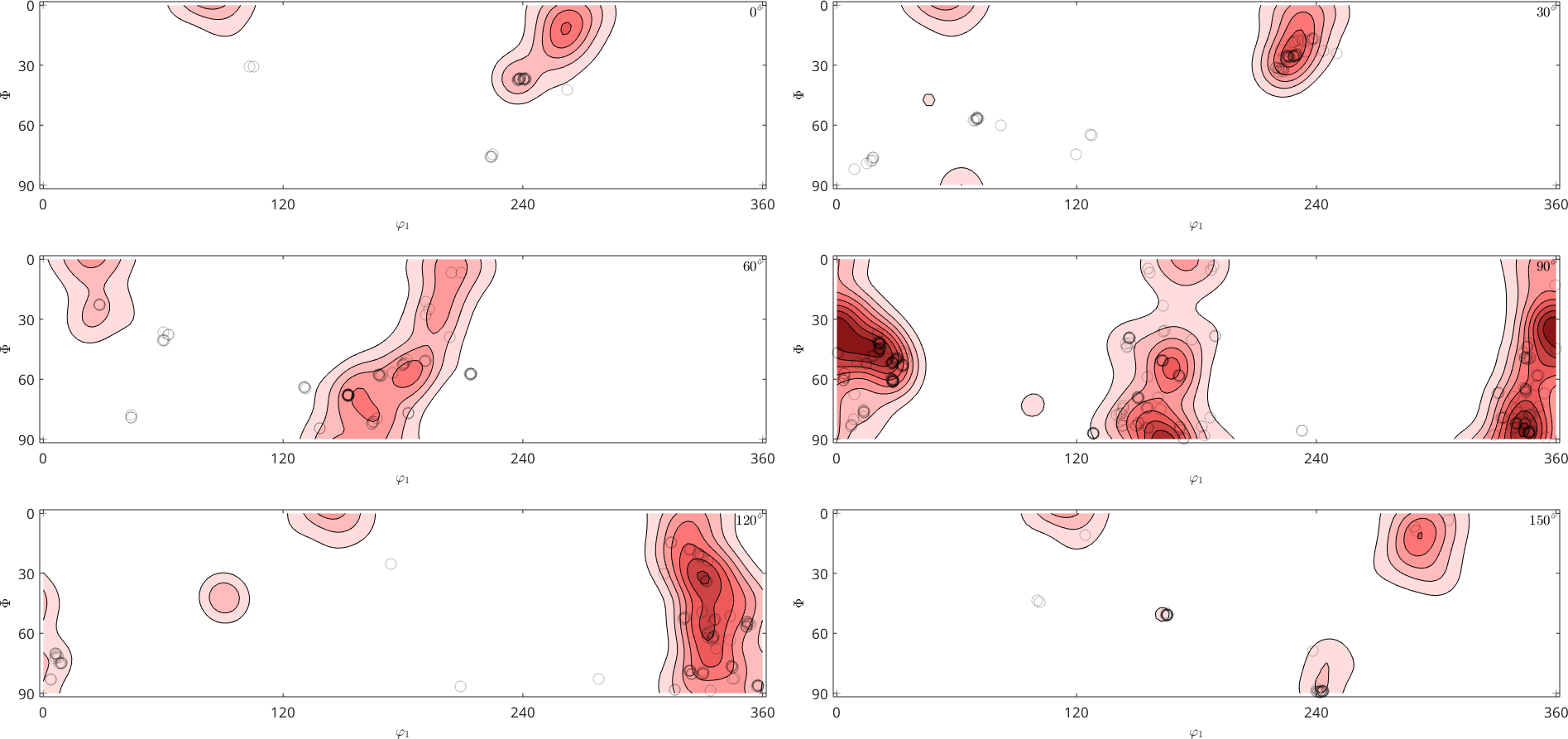
Each section cuts through the continuous ODF. The black measurements concentrate around the same section maxima, while the kernel fills the space between them. ODF Estimation from EBSD Data treats phase selection, correlated EBSD pixels, and ODF interpretation in detail.
Weights decide what population the density describes
A weighted sample gives some observations more mass than others. Grain orientations make the physical choice clear. Equal weights answer "what fraction of grains has this orientation?" Pixel-count weights approximate "what fraction of the mapped area has this orientation?"
mtexdata titanium silent
grains = calcGrains(ebsd);
indexedGrains = grains('indexed');

odfEqual = calcDensity(indexedGrains.meanOrientation,'silent');
odfByPixel = calcDensity(indexedGrains.meanOrientation,...
  'weights',indexedGrains.numPixel,'silent');

weighting = ["equal grains";"grain pixel count"];
peakMRD = [max(odfEqual);max(odfByPixel)];
table(weighting,peakMRD)
ans =
2×2 table
weighting peakMRD
___________________ _______
"equal grains" 7.6274
"grain pixel count" 8.9863The unequal peaks show that weighting changes the estimated population, not just the plotting style. On a regular map, pixel count is proportional to mapped area. State the sampling unit before interpreting an ODF.
Parametric estimation answers a different question
Kernel estimation assumes smoothness but does not prescribe one global shape. Parametric density estimation instead assumes that the unknown density belongs to a chosen family and estimates that family's parameters.
For a Gaussian, those parameters are the mean and standard deviation. The analogous models on spheres and in orientation space are Bingham distributions. See Spherical Bingham Distribution and Bingham ODFs for fitting and checking those models.
The maths behind kernel density estimation
For equally weighted samples \(x_1,\ldots,x_N\) and a normalized kernel \(\psi\), the estimate is
\[ f_N(x) = \frac{1}{N} \sum_{n=1}^N \psi(x-x_n). \]
Each observation contributes the same total mass. The kernel decides how far that mass spreads. For non-negative weights \(w_n\), MTEX replaces the equal average by a normalized weighted sum.
On the rotation group, let \(o_n\) be orientations and let \(\psi\) be a radially symmetric kernel. The weighted ODF estimate is
\[ f(o) = \frac{1}{\sum_{j=1}^{N} w_j} \sum_{n=1}^{N} w_n \psi(o o_n^{-1}). \]
MTEX also accounts for the symmetry-equivalent representatives carried by each orientation. Different phases generally have different crystal symmetries, so estimate an EBSD-derived ODF from one selected phase at a time. Kernels on SO(3) compares the kernel families.
References
- Z. I. Botev, J. F. Grotowski, and D. P. Kroese, Kernel density estimation via diffusion, The Annals of Statistics 38 (2010), 2916--2957, gives the automatic estimator used by
calcDensityfor one-dimensional real data.
- R. Hielscher, Kernel density estimation on the rotation group and its application to crystallographic texture analysis, Journal of Multivariate Analysis 119 (2013), 119--143, derives the orientation-space estimator and its fast algorithms.
- C. Bingham, An antipodally symmetric distribution on the sphere, The Annals of Statistics 2 (1974), 1201--1225, introduces the parametric directional model used here as the alternative to a kernel estimate.
Next
Optimal Kernel Selection turns the visual bias--variance trade-off into practical choices for directional and orientation data. It also explains when automatic selection is reliable.
Citing this page.
This page is part of the documentation of
MTEX, a free and open
source MATLAB toolbox for analyzing and modeling crystallographic textures.
It was written by The MTEX Developers and is published at
https://mtex-toolbox.github.io/DensityEstimation.html.
If you use MTEX, or reuse text or figures from this page, in your research,
please cite
F. Bachmann, R. Hielscher, H. Schaeben: Texture Analysis with MTEX - Free and Open Source Software Toolbox, Solid State Phenomena 160 (2010), 63-68. 10.4028/www.scientific.net/SSP.160.63
BibTeX
@article{bachmann2010mtex,
  author  = {F. Bachmann and R. Hielscher and H. Schaeben},
  title   = {Texture Analysis with MTEX - Free and Open Source Software Toolbox},
  journal = {Solid State Phenomena},
  volume  = {160},
  pages   = {63-68},
  year    = {2010},
  doi     = {10.4028/www.scientific.net/SSP.160.63},
  url     = {https://doi.org/10.4028/www.scientific.net/SSP.160.63}
}
Other papers describing specific MTEX methods are listed under Publications — please cite the one that best fits your application. The MTEX source code is licensed under the GNU General Public License v2.0; the text and figures of this documentation are licensed under CC BY 4.0, which permits reuse — including by automated systems — provided The MTEX Developers and this page are credited.