
A spherical grid is a finite list of directions used to represent the sphere in a numerical calculation. Each direction in the list is a node. Such nodes are needed to integrate a spherical function, sample one, or draw it.
A sphere cannot be covered by one rectangular angular mesh without distortion or a coordinate singularity. Grid constructions balance node spacing against other useful properties. These include equal-area cells, hierarchical structure, and regular indexing in spherical angles.
Read Vectors first for the MTEX direction model. Spherical Projections explains the upper-hemisphere view. The examples construct directions on the complete sphere. The plot option 'upper' hides the lower hemisphere; it does not identify a direction with its negative. That distinction is explained in Axes.
For these figures, the plotting convention lays the reference frame out with y up and x to the right. It does not alter the constructed nodes.
plottingConvention.default('y↑→x');Four Constructions
MTEX offers the regularS2Grid and the equispacedS2Grid. Two further choices are the HEALPixS2Grid and fibonacciS2Grid.
The regular grid is a tensor product of polar and azimuth angles. The equispaced grid changes the number of azimuth steps from one latitude to the next. HEALPix supplies the centres of hierarchical, equal-area, iso-latitude pixels. The Fibonacci grid follows a golden-angle spiral.
Each constructor accepts a target angular resolution. The target does not guarantee one exact nearest-neighbour distance. Each construction adjusts or rounds it according to its own geometry.
% a regular grid in the two spherical angles
grids{1} = regularS2Grid('resolution',7*degree);

% the MTEX equispaced grid
grids{2} = equispacedS2Grid('resolution',7*degree);

% the HEALPix grid
grids{3} = HEALPixS2Grid('resolution',7*degree);

% the Fibonacci grid
grids{4} = fibonacciS2Grid('resolution',7*degree);

gridNames = {'regular','equispaced','HEALPix','Fibonacci'};
The upper-hemisphere view makes the different node patterns visible.
plot(grids{1},'upper','layout',[1 4])
mtexTitle(gridNames{1})

for k = 2:4
  nextAxis
  plot(grids{k},'upper')
  mtexTitle(gridNames{k})
end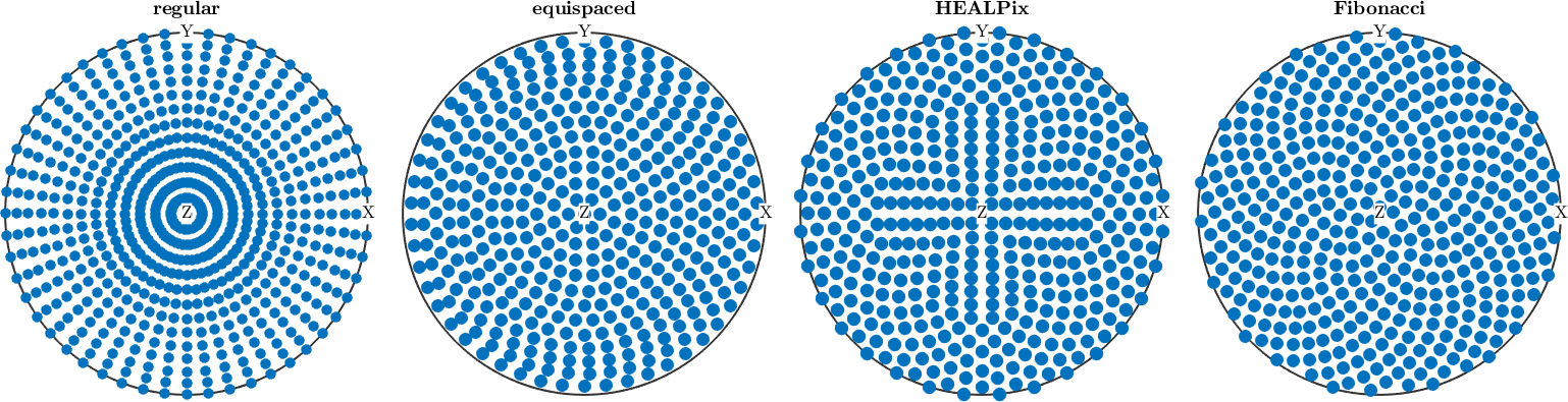
Notice how the latitude rows of the regular grid converge near the centre. At the pole, every azimuth represents the same direction. The equispaced and HEALPix patterns reduce the number of nodes on shorter latitude rings. The Fibonacci spiral has no latitude-ring structure.
The requested resolution also produces different numbers of nodes.
nodeCounts = cellfun(@length,grids)nodeCounts =
1404 812 768 827At \(7^{\circ}\) the four constructions contain 1404, 812, 768 and 827 nodes, respectively. These counts include both hemispheres. They reflect how each constructor interprets the target resolution and are not by themselves a ranking of grid quality.
Comparison of Uniformity
Node uniformity can be measured instead of only judged from a plot. Here every node receives the same weight. Density Estimation smooths the resulting discrete measure into a function on the sphere. MTEX normalizes that function to have mean value 1. A uniform equal-weight node measure should therefore be close to the constant 1.
This diagnostic measures equal-weight node placement at the chosen halfwidth. It does not test cell areas, nearest-neighbour distances, or the accuracy of a quadrature rule.
for k = 1:4
  density(k) = calcDensity(grids{k},'halfwidth',5*degree);
end

clf
for k = 1:4
  plot(density(k),'upper','layout',[2,2]);
  mtexTitle(gridNames{k})
  if k < 4, nextAxis, end
end
setColorRange('equal')
mtexColorbar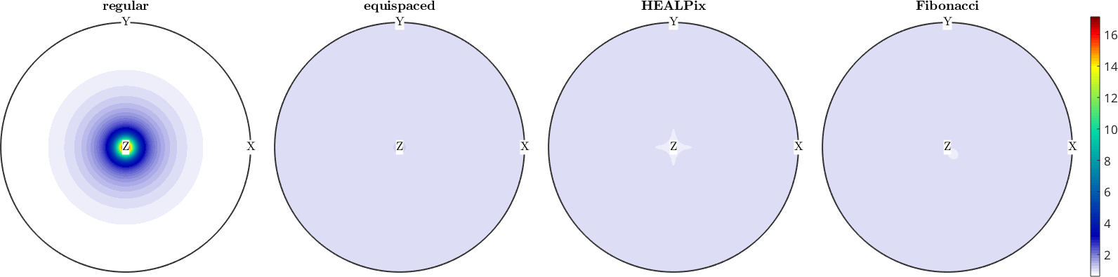
All four panels use the same colour range. The regular grid has a strong maximum at the pole, whereas the other three panels remain close to the uniform value 1. The numerical comparison below uses the complete sphere, not only the displayed upper hemisphere.
The \(L^2\) norm gives the square root of the integrated squared deviation.
l2Deviation = norm(density-1).'l2Deviation =
4.0141 0.0317 0.0426 0.0201The integrated absolute deviation is an \(L^1\) measure of the same error.
l1Deviation = sum(abs(density-1)).'l1Deviation =
5.7668
0.0600
0.0674
0.0320At a \(5^{\circ}\) halfwidth, the \(L^2\) deviations are 4.0141, 0.0317, 0.0426 and 0.0201. The \(L^1\) deviations are 5.7668, 0.0600, 0.0674 and 0.0320. The regular grid is about two orders of magnitude less uniform by both measures in this experiment. The Fibonacci grid has the smallest deviation.
This comparison is not a universal ranking. Changing the resolution or smoothing halfwidth changes the numbers, and a downstream algorithm may require cell areas, quadrature weights, or a particular grid structure.
Choosing a Grid
Use a regular grid when values must sit on a rectangular raster in the two spherical angles, for example for a surface or contour representation. Use an equispaced or Fibonacci grid when nearly uniform equal-weight nodes matter more than rectangular indexing. Use HEALPix when the centres of its standard equal-area pixelization are required.
A nearly uniform point set is not automatically a quadrature rule. If an integral must be exact for a specified class of functions, use the nodes and weights prescribed by that integration method.
Further Reading
- E. B. Saff and A. B. J. Kuijlaars, Distributing many points on a sphere, The Mathematical Intelligencer 19(1), 5-11, 1997. This article surveys competing meanings of a well-distributed point set.
- K. M. Górski et al., HEALPix: A Framework for High-Resolution Discretization and Fast Analysis of Data Distributed on the Sphere, The Astrophysical Journal 622, 759-771, 2005. This paper defines HEALPix.
- R. Swinbank and R. J. Purser, Fibonacci grids: A novel approach to global modelling, Quarterly Journal of the Royal Meteorological Society 132, 1769-1793, 2006. This paper develops the Fibonacci construction.
- V. I. Lebedev and D. N. Laikov, A quadrature formula for a sphere of the 131st algebraic order of accuracy, Doklady Mathematics 59(3), 477-481, 1999. This paper illustrates nodes designed together with weights and an exactness criterion.
Next
Grids on the rotation group are covered in Orientation Grids. Those grids can respect crystal symmetry. Choosing informative nodes for a spherical function is a different question, treated in Sampling.
Citing this page.
This page is part of the documentation of
MTEX, a free and open
source MATLAB toolbox for analyzing and modeling crystallographic textures.
It was written by The MTEX Developers and is published at
https://mtex-toolbox.github.io/VectorGrids.html.
If you use MTEX, or reuse text or figures from this page, in your research,
please cite
F. Bachmann, R. Hielscher, H. Schaeben: Texture Analysis with MTEX - Free and Open Source Software Toolbox, Solid State Phenomena 160 (2010), 63-68. 10.4028/www.scientific.net/SSP.160.63
BibTeX
@article{bachmann2010mtex,
  author  = {F. Bachmann and R. Hielscher and H. Schaeben},
  title   = {Texture Analysis with MTEX - Free and Open Source Software Toolbox},
  journal = {Solid State Phenomena},
  volume  = {160},
  pages   = {63-68},
  year    = {2010},
  doi     = {10.4028/www.scientific.net/SSP.160.63},
  url     = {https://doi.org/10.4028/www.scientific.net/SSP.160.63}
}
Other papers describing specific MTEX methods are listed under Publications — please cite the one that best fits your application. The MTEX source code is licensed under the GNU General Public License v2.0; the text and figures of this documentation are licensed under CC BY 4.0, which permits reuse — including by automated systems — provided The MTEX Developers and this page are credited.