
An inverse pole figure fixes a direction in the specimen and asks which crystal direction points along it. It asks the pole-figure question in reverse. It is the natural view when one specimen direction is physically important. Examples include the normal of a rolled sheet, a loading axis, and the surface normal of an EBSD map.
This page assumes the crystal-to-specimen coordinate map from Theory and the equivalent directions from Symmetry. It also assumes the projections from Spherical Projections. A reference frame is the coordinate system in which data are expressed. The plotting convention below lays specimen Y upward and specimen X right. It changes only the screen layout. It does not rotate the specimen or re-express the data.
plottingConvention.default('y↑→x');

rng(635);
cs = crystalSymmetry('321');

ori = orientation.rand(cs)
ori = orientation (321 → y↑→x)
Bunge Euler angles in degree
phi1 Phi phi2
309.865 57.8284 80.6927Building One by Hand
Fix the specimen Z direction. The orientation maps crystal coordinates into specimen coordinates, so its inverse maps this direction back into the crystal frame.
r = vector3d.Z;h = inv(ori) * rh = Miller (321)
h k i l
0.655 0.1369 -0.7919 0.5325The displayed Miller indices are the crystal-frame coordinates of the specimen Z direction. symmetrise applies the crystal point group. It returns every equivalent description.
hSym = h.symmetrise;

symmetryCopyCount = length(hSym)
symmetryCopyCount =
6The count is six for a general direction in point group 321. A direction on a symmetry axis can have fewer distinct copies. Several operations may give the same result there.
Plot the copies in the fundamental sector, the part of the sphere that retains one representative from each equivalent family.
plot(hSym,'fundamentalRegion','MarkerFaceColor','red');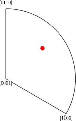
Notice one marker rather than six. Symmetry reduction maps all six copies onto the same position in the sector. They describe one crystal direction family, not six orientations.
The Shortcut
plotIPDF performs the inverse map, symmetrisation, reduction, and projection for several specimen directions at once.
plotIPDF(ori,[vector3d.X,vector3d.Y,vector3d.Z]);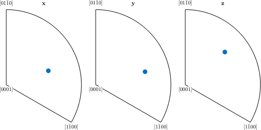
The three sectors correspond to specimen X, Y, and Z. Each marker shows which crystal direction lies along the axis named above its panel.
One marker does not determine the complete orientation. The plot loses rotation about the aligned direction. Distinct orientations can therefore occupy the same inverse pole figure position. Use 3D Plots or Section Plots when that missing information matters.
A Population as Contours
For a population, 'contourf' replaces the individual markers with a kernel density estimate on the sphere. Construct 300 orientations within \(12^\circ\) of the orientation above. This gives the density a feature worth reading.
oriPopulation = rotation.rand(300,'maxAngle',12*degree) * ori;

populationSize = length(oriPopulation)
populationSize =
300plotIPDF(oriPopulation,[vector3d.X,vector3d.Y,vector3d.Z],...
'contourf');
mtexColorbar;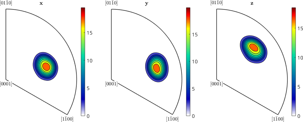
Each panel now contains one concentrated lobe rather than one marker. Its position changes because X, Y, and Z point along different crystal directions. The colour scale is in multiples of a random distribution (m.r.d.). It is a density, not a percentage of orientations at one point. Quantitative inverse pole densities from an ODF are developed in Inverse Pole Figures of an ODF.
Seeing the Symmetry Copies
By default plotIPDF draws only the fundamental sector. The option 'complete' ignores that reduction, while 'upper' restricts the result to the upper hemisphere.
plotIPDF(oriPopulation,r,'contourf','complete','upper');
mtexColorbar;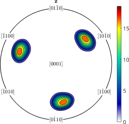
Notice that the one Z-direction lobe is repeated three times on this upper hemisphere. The complete sphere would also contain the three copies in the lower hemisphere. The six lobes are the point-group equivalents that the fundamental-sector plot folds onto one another.
The 'antipodal' flag makes the additional identification \(\mathbf{h}\sim-\mathbf{h}\). Use it only when the measurement or model cannot distinguish a crystal direction from its opposite. This is a modelling choice, not another operation of point group 321. See Axes and Antipodal Symmetry.
If an orientation carries a nontrivial specimen symmetry, plotIPDF also applies it to the fixed specimen direction. Crystal symmetry acts after the inverse map in the crystal frame. Specimen symmetry acts before it in the specimen frame. See Specimen Symmetry.
Inverse Pole Figures and EBSD Colours
An IPF map uses the same construction point by point. A colour key assigns a colour to each fundamental-sector position. The key uses one chosen specimen direction. The map therefore inherits the same information loss. Equal colours do not by themselves prove equal orientations.
The Maths Behind an Inverse Pole Figure
Let \(\mathbf{O}\) map crystal coordinates into specimen coordinates. Let \(\mathbf{C}\) be a crystal-symmetry operation, \(\mathbf{P}\) a specimen-symmetry operation, and \(\mathbf{r}\) the fixed specimen direction. Every crystal direction represented by plotIPDF has the form
\[ \mathbf{h} = \mathbf{C}\,\mathbf{O}^{-1}\mathbf{P}\,\mathbf{r}, \qquad \mathbf{C} \in \mathrm{S}_{\mathrm{c}}, \quad \mathbf{P} \in \mathrm{S}_{\mathrm{s}}. \]
This example has identity specimen symmetry. The hand construction is therefore \(\mathbf{h}=\mathbf{C}\mathbf{O}^{-1}\mathbf{r}\). Reduction to the fundamental sector keeps one representative of this family.
References
- H.-J. Bunge, Texture Analysis in Materials Science: Mathematical Methods, Butterworths, English ed., 1982, develops pole and inverse pole figures from orientation densities.
- U. F. Kocks, C. N. Tomé, and H.-R. Wenk, Texture and Anisotropy, Cambridge University Press, 1998, connects these texture representations to processing and anisotropic properties.
- A. Morawiec, Orientations and Rotations: Computations in Crystallographic Textures, Springer, 2004, develops rotations, symmetry, and elementary regions of orientation space.
- D. Chateigner, L. Lutterotti, and M. Morales, Quantitative texture analysis and combined analysis, International Tables for Crystallography H, ch. 5.3, 2019, relates orientation distributions and diffraction pole figures.
- G. Nolze and R. Hielscher, Orientations - perfectly colored, Journal of Applied Crystallography 49, 1786-1802, 2016, explains the topology and limitations of inverse-pole-figure colour keys.
- ISO 24173:2024, Microbeam analysis -- Guidelines for orientation measurement using electron backscatter diffraction, gives current guidance for reproducible EBSD orientation measurements.
Next
Continue with 3D Plots. They retain the orientation information that an inverse pole figure discards. The sector itself, and how symmetry determines its shape, is Fundamental Sector. Its counterpart for whole orientations is the Fundamental Region. For measured maps, continue with IPF Maps.
Citing this page.
This page is part of the documentation of
MTEX, a free and open
source MATLAB toolbox for analyzing and modeling crystallographic textures.
It was written by The MTEX Developers and is published at
https://mtex-toolbox.github.io/OrientationInversePoleFigure.html.
If you use MTEX, or reuse text or figures from this page, in your research,
please cite
F. Bachmann, R. Hielscher, H. Schaeben: Texture Analysis with MTEX - Free and Open Source Software Toolbox, Solid State Phenomena 160 (2010), 63-68. 10.4028/www.scientific.net/SSP.160.63
BibTeX
@article{bachmann2010mtex,
  author  = {F. Bachmann and R. Hielscher and H. Schaeben},
  title   = {Texture Analysis with MTEX - Free and Open Source Software Toolbox},
  journal = {Solid State Phenomena},
  volume  = {160},
  pages   = {63-68},
  year    = {2010},
  doi     = {10.4028/www.scientific.net/SSP.160.63},
  url     = {https://doi.org/10.4028/www.scientific.net/SSP.160.63}
}
Other papers describing specific MTEX methods are listed under Publications — please cite the one that best fits your application. The MTEX source code is licensed under the GNU General Public License v2.0; the text and figures of this documentation are licensed under CC BY 4.0, which permits reuse — including by automated systems — provided The MTEX Developers and this page are credited.