General
Neper is an open source software package for polycrystal generation and meshing developed by Romain Quey. It can be obtained from https://neper.info, where also the documentation is located.
This module provides an comfortable interface to Neper. It is used to simulate microstructures with certain parameters and load them back into MTEX for analysis and further investigation with the various tools provided by MTEX.
In order to do this, a slicing of the 3-dimensional tessellation is necessary after the simulation. The obtained 2-dimensional tessellation is processed as an object from the class grain2d.
Setting-up the Neper
If you do not want to make any further adjustments to the default values, this step could be done very easily. In this case please skip to chapter "Simulating a microstructure with Neper"
neper.init;File options: By default your Neper will work under the temporary folder of your MATLAB (MATLAB command tempdir). If you want to do your tessellations elsewhere or your tessellations are already located under another path, you can change it:
% for example
% job.filePath = 'C:\Users\user\Documents\work\MtexWork\neper';
% or
 neper.filePath = [mtexDataPath filesep 'Neper'];
By default the 3d tesselation data will be named "allgrains" with the endings .tess and .ori and the 2d slices will be named "2dslice" with the ending .tess and .ori . You can change the file names in variables fileName3d and fileName2d.
neper.fileName3d = 'my100grains';Tessellation options
The outer geometry of the volume can be controlled by the field neper.geometry. Default is "cube(1,1,1)". Other option are "cylinder(h,d,numFaces)" and "sphere(d,numFaces)".
neper.geometry = "cube(4,4,2)";Neper uses an id to identify the tessellation. This integer value "is used as seed of the random number generator to compute the (initial) seed positions" (neper.info/doc/neper_t.html#cmdoption-id) By default the tessellation id is always 1.
neper.id = 529;Neper allows to specify the morphological properties of the cells. See https://neper.info/doc/neper_t.html#cmdoption-morpho for more information. By default grain growth is used, that is an alias for:
neper.morpho = 'diameq:lognormal(1,0.35),1-sphericity:lognormal(0.145,0.03)';Simulating a microstructure with Neper
The tessellation is executed by the command simulateGrains. There are two option to call it.
- by an ODF and the number of grains
- by a list of orientations. In this case the length of the list determines the number of grains.
odf = SO3Fun.dubna
numGrains = 1000;

grains = neper.simulateGrains(numGrains,odf,'silent')
odf = SO3FunRBF (Quartz → y↑→x)
multimodal components
kernel: de la Vallee Poussin, halfwidth 5°
center: 19848 orientations, resolution: 5°
weight: 1
grains = grain3d
Phase Grains Volume Mineral Symmetry Crystal reference frame
2 1000 32 Quartz 321 X||a*, Y||b, Z||c*
boundary faces: 7131
Properties: meanRotationplot the grains
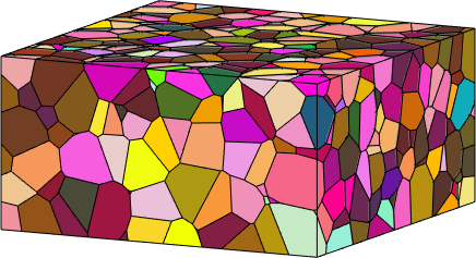
Lets visualize the grains and adjust a nice view point.
clf
plot(grains,grains.meanOrientation)

how2plot = plottingConvention.default3D;
setCamera(how2plot)
Slicing
We may generate arbitrary slices of the three dimensional grains using the command slice. It is called by giving the normal vector [a,b,c] of the plane and either a point that lies in the plane or the distance of the plane to the origin.
% the normals of the slices
N = [vector3d(0,0,1),vector3d(1,-1,0),vector3d(2,2,4)];

% make all slices passing through this point
A = vector3d(2,2,1);

grains001 = grains.slice(N(1),A);
grains1_10= grains.slice(N(2),A);
grains224 = grains.slice(N(3),A)
grains224 = grain2d (y↑→x)
Phase Grains Pixels Mineral Symmetry Crystal reference frame
2 222 222 Quartz 321 X||a*, Y||b, Z||c*
boundary segments: 669 (118 µm)
inner boundary segments: 0 (0 µm)
triple points: 393
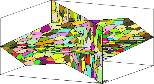
Properties: meanRotation, Id3dthe resulting slices are grain maps which we can visualize in 3d
plot(grains001,grains001.meanOrientation,'micronbar','off');
hold on
plot(grains1_10,grains1_10.meanOrientation);
hold on
plot(grains224,grains224.meanOrientation);
hold off

% set camera
setCamera(how2plot)
Warning: still can not concatenate grains on different slices
Warning: still can not concatenate grains on different slices
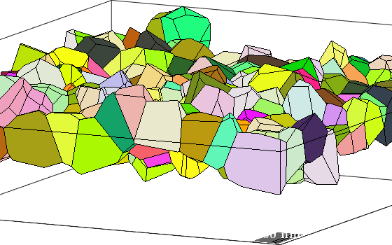
plot all grains intersecting a plane
inPlane = grains.intersected(N(1),A);

plot(grains001,grains001.meanOrientation,'micronbar','off');
hold on
plot(grains(inPlane),grains(inPlane).meanOrientation)
hold off

% set camera
setCamera(how2plot)