Diffraction counts are not pole densities. The detector also records background radiation, and tilting the specimen may reduce the measured intensity through defocusing. Isolated bad measurements and an unknown scale introduce further errors.
This page prepares measured pole figures for ODF reconstruction. It assumes the pole-figure idea from Pole Figures and the import checks from Import.
A PoleFigure behaves like an array of measured values. Pole figures can be selected, added and scaled, while individual values can be selected, overwritten or deleted.
plottingConvention.default('y←↑x');
mtexdata geesthacht

% plot the four entries in the imported object
plot(pf)
mtexColorbar
pf = PoleFigure (y←↑x)
crystal symmetry : m-3m
h = (104), r = 679 × 1 points
h = (104), r = 16 × 1 points
h = (110), r = 679 × 1 points
h = (110), r = 16 × 1 points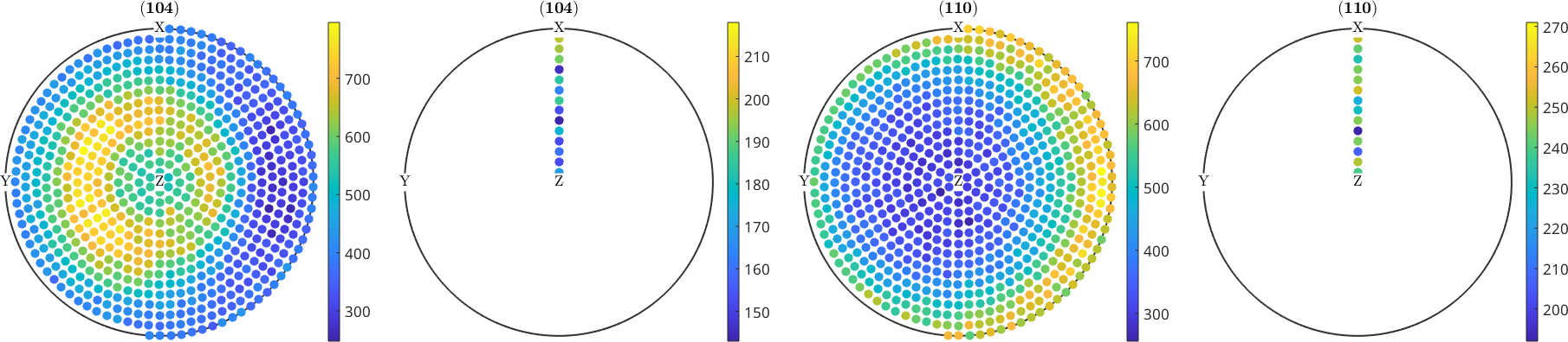
Splitting signal and background
The display and plot show four entries. The first and third are the two complete intensity scans, with 679 specimen directions each. The second and fourth are sparse background scans with 16 directions each.
Each background panel is a single radial line of points running from the centre of the disc outward: the 16 directions share one azimuth and differ only in polar angle. They belong to the complete scan with the same Miller index. A cell inside parentheses selects entries of the PoleFigure object.
pf_complete = pf({1,3});
pf_background = pf({2,4});
Arithmetic with pole figures
Arithmetic uses the same syntax as arithmetic with numbers. The following weighted sum demonstrates addition and scaling without changing pf.
pf_weighted = 2*pf({1}) + 3*pf({3});The weights above are arbitrary and the two entries have different Miller indices. This is an API example, not a physical correction or an example of an unresolved diffraction peak.
Background and defocusing
correct applies correction measurements that have already been obtained. It does not infer background or defocusing from the measured pole figure.
With 'background', MTEX interpolates each sparse background scan onto the directions of its complete scan and subtracts it. Because these background points differ only in polar angle, that interpolation is a spline in the polar angle alone. The Geesthacht data contain the background measurements needed for this operation.
pf = correct(pf_complete,'background',pf_background);

% compare the first scan before and after background subtraction
plot([pf_complete({1}),pf({1})],'layout',[1,2])
setColorRange('equal');
mtexColorbar

correctedI = pf.intensities;
fprintf('Corrected counts: min %.0f, mean %.0f, max %.0f\n',...
  min(correctedI(:)),mean(correctedI(:)),max(correctedI(:)));
Corrected counts: min 7, mean 273, max 631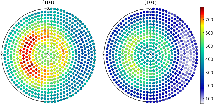
The left panel is the raw (104) scan and the right panel is the corrected scan on the same colour range. Background subtraction preserves the broad intensity pattern while lowering every value. The corrected counts run from 7 to 631, with an arithmetic mean of 273.
Defocusing is different: it is a tilt-dependent loss of signal, so the correction is a division. Supply a defocusing measurement and, when available, its own background measurement:
pf = correct(pf,'background',pf_bg,...
  'defocusing',pf_def,'defbg',pf_def_bg);
MTEX subtracts pf_bg from pf, subtracts pf_def_bg from pf_def, and divides the first result by the second. The correction measurements must match the pole figures physically; interpolation only adapts their sampled directions.
Normalization
Pole density is reported in multiples of a random distribution (mrd). Its mean over a complete pole figure is 1, so normalize divides each complete scan by its quadrature-weighted mean.
pf_normalized = normalize(pf);
plot(pf_normalized)
mtexColorbar

normalizedI = pf_normalized.intensities;
normalizedMean = mean(pf_normalized);
fprintf(['Normalized mrd: min %.2f, max %.2f; ',...
  'pole-figure means %.2f and %.2f\n'],...
  min(normalizedI(:)),max(normalizedI(:)),normalizedMean);
Normalized mrd: min 0.03, max 2.15; pole-figure means 1.00 and 1.00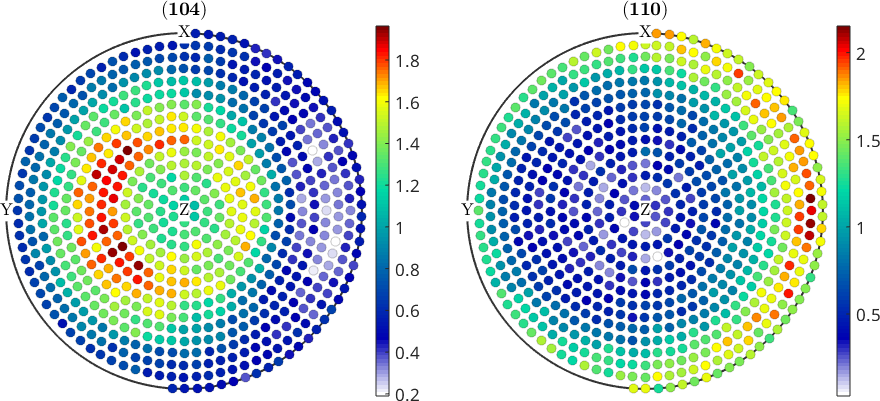
The pattern has not moved; only the colour scale has changed. Values now run from 0.03 to 2.15 mrd, and both pole figures have mean 1. They can therefore be compared with normalized measurements from another specimen.
Incomplete pole figures
Direct normalization fails for an incomplete pole figure. The unmeasured part of the sphere also carries pole density, and its contribution is exactly what is unknown.
One route is to reconstruct an ODF first. The ODF fills in the unmeasured part, and normalize(pf,odf) determines the scale against recalculated values at the measured directions. ODF reconstruction is explained in ODF Reconstruction.
odf = calcODF(pf,'silent');
pf_normalized_odf = normalize(pf,odf);

plot(pf_normalized_odf)
mtexColorbar

odfNormalizedMean = mean(pf_normalized_odf);
normalizationDifference = 100*max(abs(odfNormalizedMean-1));
fprintf('Largest ODF-based scale difference: %.2f percent\n',...
  normalizationDifference);
Largest ODF-based scale difference: 0.33 percent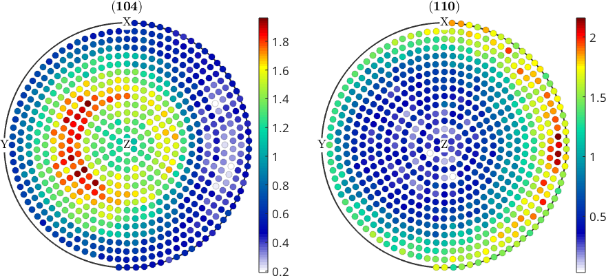
These pole figures are complete, so the direct and ODF-based scales differ by at most 0.33 percent. Their plots are consequently almost indistinguishable. On incomplete data the two procedures need not agree.
Outliers
A single bad measurement can distort a reconstruction because the solver has no reason to distrust it. isOutlier marks values that disagree with the mean of their neighbourhood.
The default threshold is two standard deviations for each pole figure. Review the flagged points in the measurement context instead of treating the default as an automatic quality criterion.
To make the operation visible, first spoil 100 random measurements.
ind = randperm(pf.length,100);
factor = 3+rand(100,1);
pf(ind).intensities = pf(ind).intensities(:) .* factor;

plot(pf)
mtexColorbar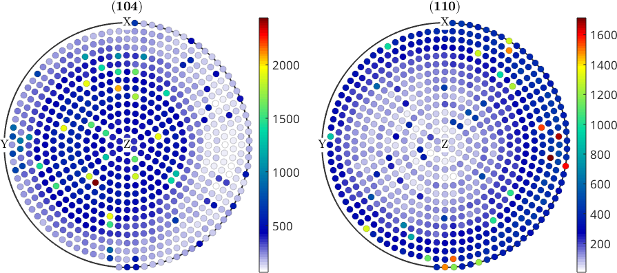
The spoiled measurements appear as isolated bright dots above the broad texture pattern. Deleting selected entries uses assignment of the empty matrix, as it does for an ordinary MATLAB array.
condition = isOutlier(pf);
nFirstPass = nnz(condition);
fprintf('Outliers removed on first pass: %d\n',nFirstPass);
pf(condition) = [];

plot(pf)
mtexColorbar
Outliers removed on first pass: 48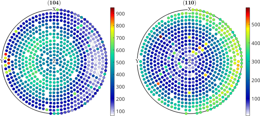
The first pass removes 55 of the 100 inserted values. An outlier beside another outlier raises the local mean and can hide behind it. Recomputing the condition after deletion catches 26 more.
condition = isOutlier(pf);
nSecondPass = nnz(condition);
fprintf('Outliers removed on second pass: %d\n',nSecondPass);
pf(condition) = [];

plot(pf)
mtexColorbar
Outliers removed on second pass: 29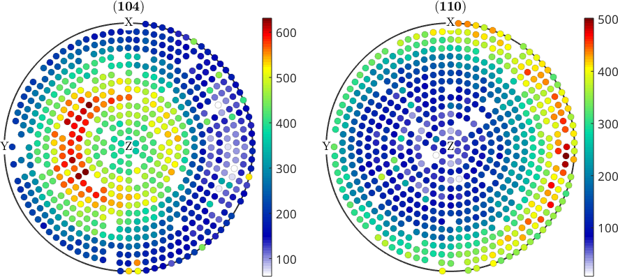
Most isolated bright points have disappeared after the second pass. The remaining inserted values were not separated far enough from their local neighbourhood to pass this particular threshold.
Deletion removes both the intensity and its specimen direction. It does not replace the value by an interpolated estimate.
Any other condition
Nothing about indexed assignment is specific to outliers. Any logical condition on the intensities can select values for deletion or replacement.
The next threshold is deliberately artificial: it demonstrates assignment by capping counts at 500, not a recommended experimental correction.
condition = pf.intensities > 500;
nCapped = nnz(condition);
nRemaining = numel(pf.intensities);
fprintf('Values capped at 500: %d of %d\n',nCapped,nRemaining);
pf(condition).intensities = 500;

plot(pf)
mtexColorbar
Values capped at 500: 99 of 1281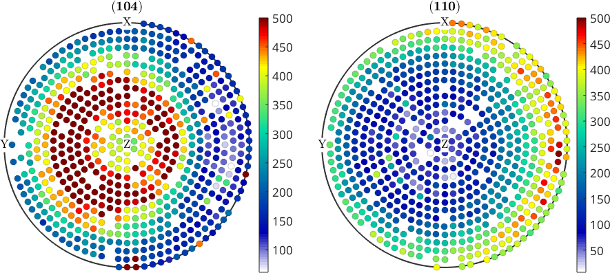
The cap affects 94 of the remaining 1277 measurements. They now share the same top colour, flattening the bright parts of the plot and showing why a numerical condition needs a physical justification.
Rotating pole figures
A reference frame is the coordinate system in which the specimen directions are expressed. If import assigned the wrong specimen frame, fix the import as described in Import whenever possible.
The following example deliberately rotates the measured directions by 100 degrees about the x-axis. This moves the data; it is not a change of plotting convention, which only controls where axes are drawn.
rot = rotation.byAxisAngle(xvector,100*degree);
pf_rotated = rotate(pf,rot);

plot(pf_rotated,'antipodal')
mtexColorbar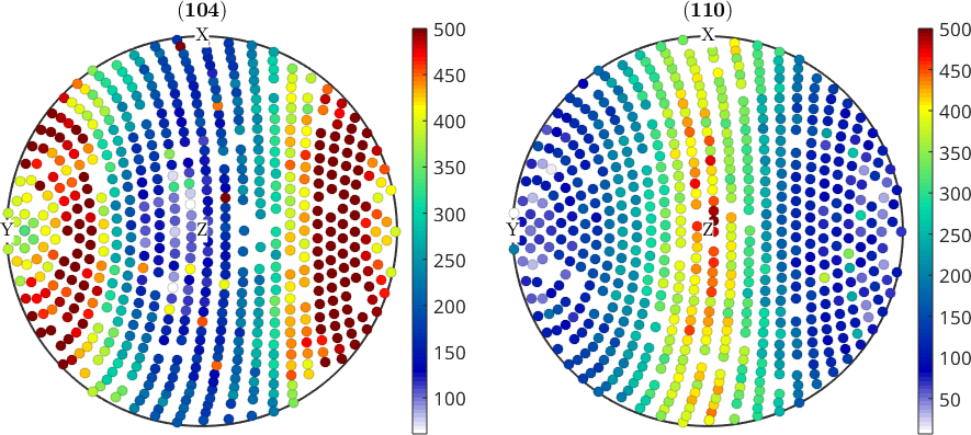
rotate leaves the intensities unchanged and applies the rotation to their measured directions. The measured cap tips across the equator, and 'antipodal' folds the part below the equator back into the same disc.
Both panels come out filled edge to edge, and the vertical arcs across them are the rotated ring sampling rather than gaps in it. Drop 'antipodal' and the (110) panel opens over the part of the sphere that was never measured. That is why correcting the specimen frame at import is preferable to an avoidable rotation later.
Further reading
- ASTM International, ASTM E81-96(2024): Standard Test Method for Preparing Quantitative Pole Figures. It distinguishes complete, partial and calculated pole figures and describes experimental preparation.
- H.-J. Bunge, Texture Analysis in Materials Science: Mathematical Methods, Butterworths, English ed., 1982. It gives the classical definitions of pole density, normalization and ODF inversion.
- A. A. Saleh, V. Q. Vu and A. A. Gazder, Correcting intensity loss errors in the absence of texture-free reference samples during pole figure measurement, Materials Characterization 118, 425-430, 2016. It explains background, tilt-dependent intensity loss and reference-sample corrections.
- D. Chateigner, L. Lutterotti and M. Morales, Quantitative texture analysis and combined analysis, International Tables for Crystallography, Volume H, chapter 5.3, 2019. It connects diffraction intensity, instrumental corrections, normalized pole density and the ODF forward model.
Citing this page.
This page is part of the documentation of
MTEX, a free and open
source MATLAB toolbox for analyzing and modeling crystallographic textures.
It was written by The MTEX Developers and is published at
https://mtex-toolbox.github.io/PoleFigureCorrection.html.
If you use MTEX, or reuse text or figures from this page, in your research,
please cite
F. Bachmann, R. Hielscher, H. Schaeben: Texture Analysis with MTEX - Free and Open Source Software Toolbox, Solid State Phenomena 160 (2010), 63-68. 10.4028/www.scientific.net/SSP.160.63
BibTeX
@article{bachmann2010mtex,
  author  = {F. Bachmann and R. Hielscher and H. Schaeben},
  title   = {Texture Analysis with MTEX - Free and Open Source Software Toolbox},
  journal = {Solid State Phenomena},
  volume  = {160},
  pages   = {63-68},
  year    = {2010},
  doi     = {10.4028/www.scientific.net/SSP.160.63},
  url     = {https://doi.org/10.4028/www.scientific.net/SSP.160.63}
}
Other papers describing specific MTEX methods are listed under Publications — please cite the one that best fits your application. The MTEX source code is licensed under the GNU General Public License v2.0; the text and figures of this documentation are licensed under CC BY 4.0, which permits reuse — including by automated systems — provided The MTEX Developers and this page are credited.