
Read a population of EBSD orientations in projections, sections, and three-dimensional orientation space.
An EBSD map answers where an orientation was measured. The plots on this page discard position and ask which orientations occur. A pole figure makes a preferred crystal direction easy to see, an inverse pole figure makes alignment with a specimen direction easy to see, and an orientation-space plot can reveal components or fibres.
This page assumes phase selection from Select EBSD data and the crystal-to-specimen map from Orientation theory. A reference frame is the coordinate system in which the data are expressed. Check it as described in Reference Frame before reading specimen directions from any plot.
A plotting convention states how that frame is laid out on screen. The convention below draws specimen Y upward and specimen X to the right. It changes the screen layout, but does not rotate the specimen or re-express the orientations.
plottingConvention.default('y↑→x');
mtexdata forsterite silent
The orientation list
Select the forsterite phase and display its orientations. The summary reports one orientation per indexed measurement, together with the crystal symmetry carried by the list.
ori = ebsd('Fo').orientationsori = orientation (Forsterite → y↑→x)
size: 152345 × 1There are 152345 orientations. Drawing all of them as markers would make an opaque blot, so the plotting commands take a random sample and report its size. The option 'points' requests a particular sample size, while 'all' draws the complete list.
The automatic sample size depends on the plot. A pole figure divides 10000 by the number of symmetry elements, which gives 1250 for the eight elements of forsterite, and an inverse pole figure divides 100000 the same way. Section and three-dimensional plots ignore symmetry and take 2000. The two constants are conventions of the plotting commands, not a statement about the data.
Pole figures
A pole figure fixes a crystal direction and asks where it points in the specimen. Each sampled orientation maps the \((100)\) pole into the specimen frame. plotPDF also accounts for the crystallographically equivalent poles.
plotPDF(ori,Miller(1,0,0,ori.CS))I'm plotting 1250 random orientations out of 152345 given orientations
You can specify the number of points by the option "points".
The option "all" ensures that all data are plotted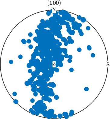
The poles form a broad girdle through specimen Y and Z, while the rim near specimen X is sparse. The forsterite \(a\) axes therefore lie preferentially in the specimen Y--Z plane and rarely along specimen X. If X, Y, and Z denote rolling, transverse, and normal directions, respectively, this is the transverse--normal plane rather than the rolling direction.
One pole figure does not determine a complete orientation. It discards the rotation about the chosen pole; see Pole Figures for the construction and its symmetry rules.
Inverse pole figures
An inverse pole figure fixes a specimen direction and asks which crystal direction points along it. plotIPDF draws the answer in a fundamental sector, which contains one representative of each family of crystal-symmetry-equivalent directions.
plotIPDF(ori,xvector)I'm plotting 12500 random orientations out of 152345 given orientations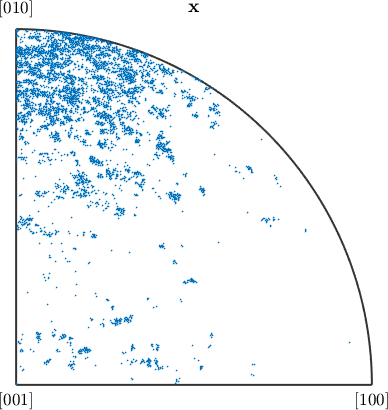
The points crowd towards \([010]\) and thin out towards \([100]\). This is the previous figure read from the other end: specimen X is rarely the forsterite \(a\) axis. Like a pole figure, an inverse pole figure discards rotation about the aligned direction. The full construction is developed in Inverse Pole Figures.
Sections through orientation space
Orientation space has three dimensions. A section plot replaces it with a stack of two-dimensional slices, so it retains all three orientation coordinates across the stack rather than projecting away one rotation. plotSection draws points within a finite tolerance of each slice. An orientation can therefore miss every panel, and a symmetry-equivalent representative can appear more than once.
The sigma sections used here are introduced in Orientation Sections and treated in detail in Sigma Sections.
plotSection(ori,'points',1000,'sigma','sections',9)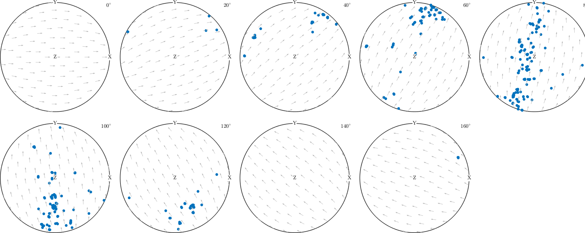
MTEX first samples 1000 orientations and then tests the section tolerance and symmetry representatives. The thousand points asked for are distributed over the nine sections, not drawn in each of them. The number of visible markers is therefore not necessarily 1000. The strongest clusters continue through adjacent central sections, which shows that they occupy finite regions of orientation space rather than one mathematical slice.
The orientation space directly
The same orientations can be scattered into one three-dimensional plot. For an orientation with crystal and specimen frames, the default is the symmetry-reduced region in Bunge Euler angles.
scatter(ori)plot 2000 random orientations out of 152345 given orientations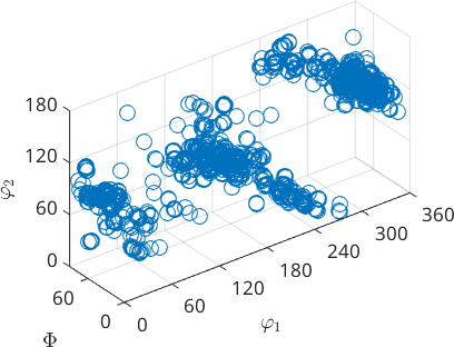
Several compact clouds are joined by thinner populations. Many nearby EBSD measurements often come from the same grain, but a cloud is not a grain label because position has already been discarded. Euler space also distorts distances strongly near \(\Phi = 0\), so use this plot to locate clusters rather than to judge their angular separation.
Passing 'axisAngle' or 'Rodrigues' selects those parametrizations. The option 'center' moves the symmetry-reduced region being drawn. See 3D Orientation Plots for their geometry.
The same plots for grains
A grain is a phase-homogeneous, spatially connected region of EBSD pixels produced by segmentation. Each grain carries a mean orientation, so the plotting commands above also accept a grain-mean list. The segmentation criterion determines which grains and means exist; choose it for the material as explained in Grain Reconstruction.
grains = calcGrains(ebsd);
foGrains = grains('Fo');
Compare equally sized random samples. The blue markers represent individual measurements and the orange markers represent grain means.
plotIPDF(ori,xvector,'points',1000,'MarkerSize',3,...
  'MarkerColor','blue');
hold on
plotIPDF(foGrains.meanOrientation,xvector,'points',1000,'MarkerSize',3,...
  'MarkerColor','orange');
hold off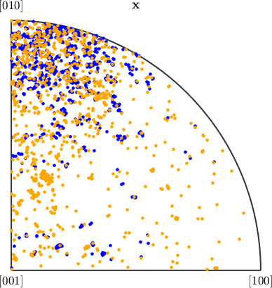
The clouds cover broadly the same sector, but not with the same weight. On this regular map, sampling measurements approximately weights each grain by its mapped area because a large grain contributes many pixels. Sampling grain means gives every segmented grain one vote, whatever its area. The orange means are consequently more evenly spread and reach regions where the blue measurement population is thin.
Neither view is universally correct. Pixel weighting estimates an area fraction in this section; equal grain weighting describes the population of segmented grains. It is not a volume fraction unless additional stereological assumptions justify that interpretation.
Colouring the points
A scatter plot has a second visual channel. Passing one scalar per orientation colours each marker by that value. Here mad is the mean angular deviation between an indexed diffraction pattern and its solution. It is a per-measurement property, so it is selected in lockstep with ori; see Properties.
h = [Miller(1,0,0,ori.CS),Miller(1,1,0,ori.CS)];
plotPDF(ori,ebsd('Fo').mad,h,'antipodal','MarkerSize',4)
mtexColorbar('title','mean angular deviation (degree)')
I'm plotting 1250 random orientations out of 152345 given orientations
You can specify the number of points by the option "points".
The option "all" ensures that all data are plotted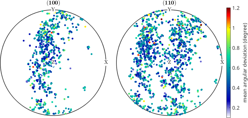
Low and high MAD values are intermingled across the main pole concentrations. There is no separate high-MAD cluster that explains the texture by itself. A high MAD flags a poor pattern fit; it does not prove that an orientation is wrong.
The same positional argument accepts a scalar per grain. Colour by the logarithm of grain area so that the wide size range remains visible.
plotSection(foGrains.meanOrientation,log(foGrains.area),...
  'sigma','sections',9,'MarkerSize',10,'all');
mtexColorbar('title','log(grain area)')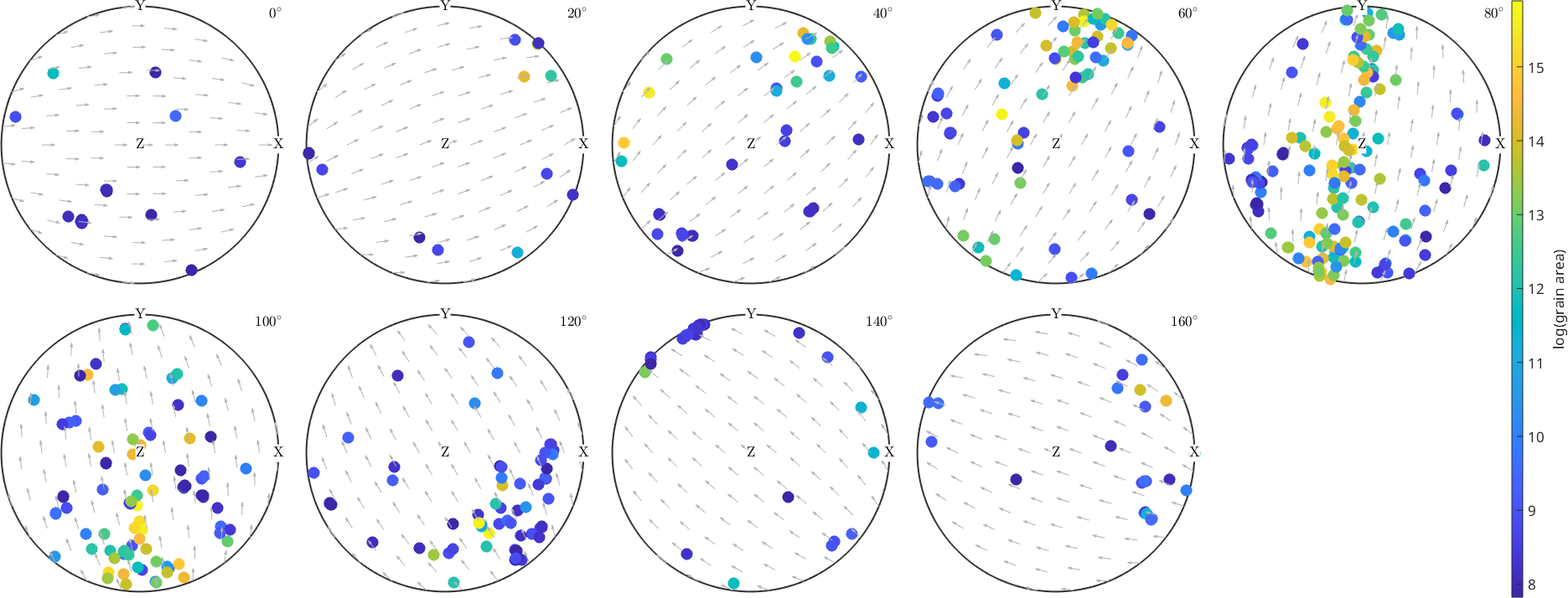
Colour changes only the marker colour; it does not change the statistical weight of that grain. The larger yellow and green grains lie mainly in the same central-section concentrations as the many smaller blue grains, while most isolated points are small. This is why grain size and orientation should be examined together rather than silently replacing one weighting by the other.
Choosing the next representation
These scatter plots are qualitative views of a finite orientation list. Pole and inverse pole figures answer directional questions but discard one rotational degree of freedom. Sections and three-dimensional plots retain three coordinates, although their geometry and symmetry reduction still matter.
For a quantitative texture, estimate an orientation distribution function (ODF), a density on orientation space, as shown in ODF Estimation. Plot Types covers marker plots in general, and Spherical Projections explains how spherical directions reach the page.
References
- H.-J. Bunge, Texture Analysis in Materials Science: Mathematical Methods, Butterworths, English ed., 1982, develops pole figures, inverse pole figures, Euler orientation space, and orientation distribution functions.
- J. Galán López and L. A. I. Kestens, A multivariate grain size and orientation distribution function: derivation from electron backscatter diffraction data and applications, Journal of Applied Crystallography 54 (2021), 148-162, distinguishes grain frequency from volume-weighted texture and treats correlations between grain size and orientation.
- ISO 24173:2024, Microbeam analysis - Guidelines for orientation measurement using electron backscatter diffraction, gives the measurement and calibration guidance required before these orientation plots can be interpreted reliably.
Next
Orientation Analysis turns these views into a test of a candidate fibre texture. Grains continues with spatially connected regions, while ODF Analysis continues with densities on orientation space.
Citing this page.
This page is part of the documentation of
MTEX, a free and open
source MATLAB toolbox for analyzing and modeling crystallographic textures.
It was written by The MTEX Developers and is published at
https://mtex-toolbox.github.io/EBSDOrientationPlots.html.
If you use MTEX, or reuse text or figures from this page, in your research,
please cite
F. Bachmann, R. Hielscher, H. Schaeben: Texture Analysis with MTEX - Free and Open Source Software Toolbox, Solid State Phenomena 160 (2010), 63-68. 10.4028/www.scientific.net/SSP.160.63
BibTeX
@article{bachmann2010mtex,
  author  = {F. Bachmann and R. Hielscher and H. Schaeben},
  title   = {Texture Analysis with MTEX - Free and Open Source Software Toolbox},
  journal = {Solid State Phenomena},
  volume  = {160},
  pages   = {63-68},
  year    = {2010},
  doi     = {10.4028/www.scientific.net/SSP.160.63},
  url     = {https://doi.org/10.4028/www.scientific.net/SSP.160.63}
}
Other papers describing specific MTEX methods are listed under Publications — please cite the one that best fits your application. The MTEX source code is licensed under the GNU General Public License v2.0; the text and figures of this documentation are licensed under CC BY 4.0, which permits reuse — including by automated systems — provided The MTEX Developers and this page are credited.