
Hold a grain up against the light and measure the width of its shadow. Turn it a little and measure again. The family of parameters on this page comes from that operation: the width of a grain as a function of direction.
|
quantity |
meaning |
|
caliper or Feret diameter in the map's length unit |
|
|
longest caliper in the map's length unit |
Unlike a fitted ellipse, which describes a grain by four numbers, the projection function keeps one value for every direction. It can therefore describe fabrics that one ellipse cannot.
This page assumes that the grains have been reconstructed and that selecting complete grains is familiar from Selecting Grains. Grain Smoothing explains why a boundary reconstructed from a pixel grid should be smoothed before its directions are measured. All measurements below describe two-dimensional grain sections, not the full three-dimensional grains.
% load sample EBSD data in its specimen plotting frame
plottingConvention.default('y↑→x');
mtexdata forsterite silent

% reconstruct grains, discard boundary grains, and smooth their outlines
[grains, ebsd] = calcGrains(ebsd,'angle',5*degree,'minPixel',5);
grains(grains.isBoundary) = [];
grains = smoothBoundary(grains('indexed'),10,'moveTriplePoints');

% plot all grains and highlight one complete grain
plot(grains)

ind = 515;
hold on
plot(grains(ind).boundary,'lineWidth',5,'linecolor','blue')
hold off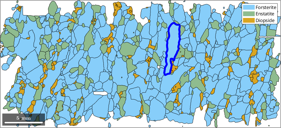
The blue outline identifies the grain used in the first measurements. Removing grains at the map edge prevents a truncated section from being mistaken for an unusually narrow or elongated grain. Smoothing suppresses the horizontal and vertical directions imposed by the measurement grid.
The caliper
The diameter is the longest distance between any two vertices of the outline. For the selected grain it is:
grainDiameter = grains(ind).diametergrainDiameter =
6.9252e+03A caliper, or Feret diameter, is the span of the grain after its vertices are projected onto a supplied direction. Traced over all directions, the caliper becomes a function. The direction is an axis, so values 180 degrees apart are identical.
close all
omega = linspace(0,180);
dir = vector3d.byPolar(90*degree,omega*degree);
plot(omega,grains(ind).caliper(dir),'LineWidth',2)
ylabel('length in \(\mu\)m','Interpreter','latex')
xlabel('projection direction in degrees')
xlim([0,180])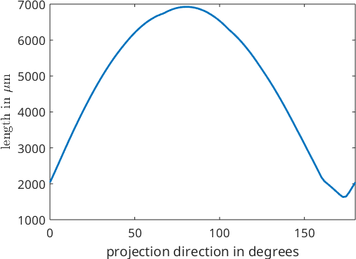
The curve of this grain runs between 1632 and 6925 µm. Its one broad maximum and one minimum over 180 degrees are characteristic of an elongated, roughly convex outline. The extrema are also available as vectors whose norm is the caliper length. The longest one is the diameter again.
caliperExtrema = [norm(grains(ind).caliper('shortest')),...
  norm(grains(ind).caliper('longest'))]

plot(grains(ind),'micronbar','off')
legend('off')

hold on
quiver(grains(ind),grains(ind).caliper('longest'),'noScaling')
quiver(grains(ind),grains(ind).caliper('shortest'),'noScaling')
hold off
caliperExtrema =
1.0e+03 *
1.6317 6.9252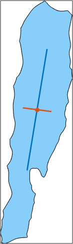
The long arrow joins the two most distant vertices. The short arrow shows the minimum width and is not generally perpendicular to the long one.
Directional elongation
The relative difference between the two extrema is a simple measure of how far a grain is from having the same width in every direction. It is zero for a constant-width outline and approaches one as the minimum width becomes small. It measures directional elongation, not lobes or boundary roughness.
cMin = grains.caliper('shortest');
cMax = grains.caliper('longest');
caliperAnisotropy = (norm(cMax) - norm(cMin))./norm(cMax);

plot(grains,caliperAnisotropy,'micronbar','off')
mtexColorbar('title','(c_{max} - c_{min}) / c_{max}')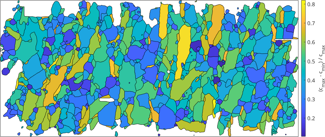
Grains with similar maximum and minimum widths plot near zero. High values mark sections whose longest span is much greater than their minimum width.
Three ways to say which way a grain points
The longest caliper and the long axis of the fitted ellipse usually agree, but not always. For rectangular particles they disagree badly: the longest caliper of a rectangle follows a diagonal. A strong alignment of rectangles can therefore produce a bimodal distribution of diagonals that no grain actually points along. The direction normal to the shortest caliper, 'shortestPerp', does not have this problem.
% load two artificial grains
testgrains = mtexdata('testgrains');
testgrains = smoothBoundary(testgrains([6 8]),10);

% compute the longest caliper and the direction normal to the shortest one
cMax = testgrains.caliper('longest');
cMinPerp = testgrains.caliper('shortestPerp');

% compare the three candidate long directions
plot(testgrains,'micronbar','off','lineWidth',2)
hold on
quiver(testgrains,cMax,'DisplayName','longest caliper','LineWidth',3)
quiver(testgrains,testgrains.longAxis,'DisplayName','long axis','LineWidth',3)
quiver(testgrains,cMinPerp,'DisplayName','perp. to shortest','LineWidth',3)
hold off
legend('Location','east')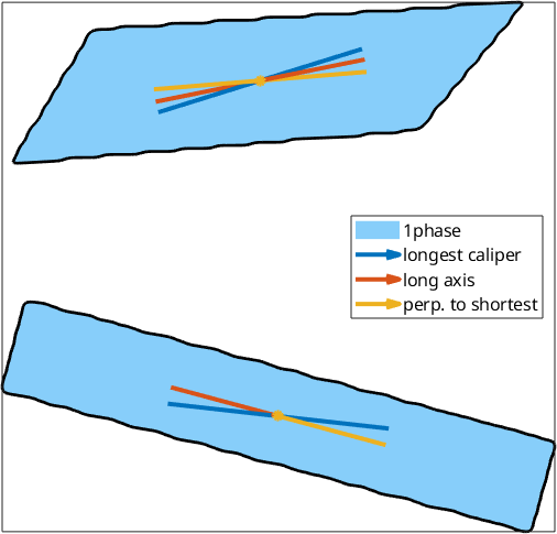
On the upper shape the three arrows point in visibly different directions. On the lower one the long axis and the perpendicular to the shortest caliper agree to a ten-thousandth of a degree, so those two arrows lie on top of each other and only the longest caliper stands apart.
Which one to use is a decision about the material: use the long axis for roughly elliptical grains and the perpendicular to the shortest caliper for grains whose flat faces define their alignment.
From grains to a particle fabric: PAROR
A shape preferred orientation, or SPO, is an alignment of grains as bodies. Projection lengths can be added over a population without first assigning one direction to every grain and without assuming that each grain is an ellipse. This construction is the PAROR method introduced by Panozzo.
caliper accepts a list of directions and returns one projection length per grain and direction. The individual functions and their average can therefore be drawn directly.
close all
omega = linspace(0,360*degree,361);
dir = vector3d.byPolar(90*degree,omega);
c = grains('Fo').caliper(dir);

subplot(1,2,1)
polarplot(omega,c,'LineWidth',2,'color',[0 0.25 0.5 0.25])
title('Forsterite')

% draw the average five times larger than its true scale
hold on
polarplot(omega,5*mean(c),'LineWidth',3,'color','k');
hold off

subplot(1,2,2)
c = grains('Enstatite').caliper(dir);
polarplot(omega,c,'LineWidth',2,'color',[0 0.25 0.5 0.25])
title('Enstatite')

% draw the average five times larger than its true scale
hold on
polarplot(omega,5*mean(c),'LineWidth',3,'color','k');
hold off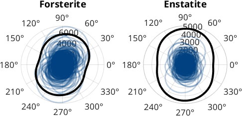
Each faint line is one grain and the black line is their average, drawn five times too large so that it remains visible. Individual grains scatter over many shapes and directions. The smooth, slightly flattened average reveals the particle fabric.
paror sums the same projection lengths over the grains and divides the curve by its maximum. A larger grain contributes a wider projection. Since a sum and a mean differ only by the number of grains, this is also the same normalized average drawn above. The normalization removes the total scale, so the result compares fabric direction and anisotropy, not grain count, phase amount, or mean grain size.
The supplied angle is the axis onto which the vertices are projected. Zero degrees is the specimen x axis, angles increase counterclockwise, and the result repeats after 180 degrees. Sampling through 360 degrees merely closes the polar curve. This is the direct form of the traditional description in which a right-handed coordinate system is rotated around the particle and the particle is projected onto its x axis.
close all
cumplF = paror(grains('fo'),omega);
cumplE = paror(grains('en'),omega);

plOpt = {'LineWidth',3,'color','k'};

subplot(2,2,1)
plot(omega/degree,cumplF,plOpt{:}); xlim([0 180]);
title('PAROR forsterite')
subplot(2,2,2)
polarplot(omega,cumplF,plOpt{:})
subplot(2,2,3)
plot(omega/degree,cumplE,plOpt{:}); xlim([0 180]);
title('PAROR enstatite')
subplot(2,2,4)
polarplot(omega,cumplE,plOpt{:})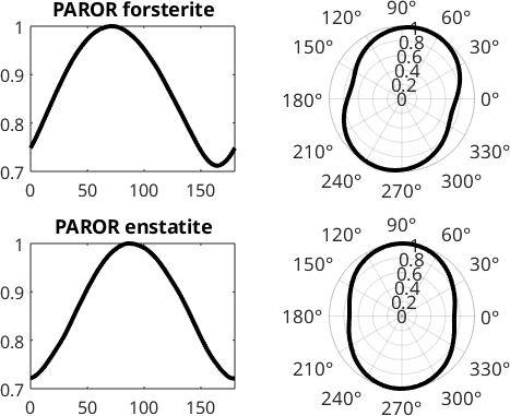
The Cartesian panels make the extrema easy to read over the independent interval from 0 to 180 degrees. The polar panels turn the same values into a visual fabric axis. The curves are normalized, so only their shape and direction should be compared.
The minimum plays the role of an average axial ratio \(b/a\) for the whole fabric. It is 1 for an isotropic projection function and becomes smaller as the fabric becomes more anisotropic.
parorMinimum = [min(cumplF),min(cumplE)]parorMinimum =
0.7118 0.7214The forsterite and enstatite minima are 0.7118 and 0.7214, a difference of about 0.01. Both phases therefore have a moderate projection anisotropy of similar strength.
The maximum marks the preferred direction of the longest projection. The normal to the minimum marks the preferred direction inferred from the shortest projection. For an orthorhombic fabric these axes coincide in the section, so their difference measures departure from orthogonal fabric axes.
Harmonic interpolation estimates the extrema between the sampled angles.
sF_Fo = S1FunHarmonic.interpolate(omega,cumplF);
[~, maxposfo] = max(sF_Fo);
[~, minposfo] = min(sF_Fo);

harmonicDirectionsFo = ...
  [mod(maxposfo,pi),mod(minposfo-pi/2,pi)] ./ degree

sF_En = S1FunHarmonic.interpolate(omega,cumplE);
[~, maxposen] = max(sF_En);
[~, minposen] = min(sF_En);

harmonicDirectionsEn = ...
  [mod(maxposen,pi),mod(minposen-pi/2,pi)] ./ degree
harmonicDirectionsFo =
71.4750 74.4500
harmonicDirectionsEn =
87.4250 88.7750For forsterite the two fitted directions are 71.5 and 74.5 degrees; for enstatite they are 87.5 and 88.8 degrees. The two directions of each phase lie within a few degrees, so both fabrics are close to orthorhombic in this section. The 16-degree difference between the preferred longest projections of the two phases is the more interesting comparison.
The same directions can be read directly from the sampled values. The sampling is one degree, so these estimates agree with the harmonic result to within that resolution.
[~, idMax] = max(cumplF);
[~, idMin] = min(cumplF);
sampledDirectionsFo = ...
  [mod(omega(idMax)./degree,180),...
  mod(omega(idMin)./degree-90,180)]

[~, idMax] = max(cumplE);
[~, idMin] = min(cumplE);
sampledDirectionsEn = ...
  [mod(omega(idMax)./degree,180),...
  mod(omega(idMin)./degree-90,180)]
sampledDirectionsFo =
72.0000 74.0000
sampledDirectionsEn =
87.0000 89.0000From boundaries to a surface fabric: SURFOR
surfor applies the same projection idea to a list of boundary segments instead of to whole grains. It weights every segment by its length and normalizes the summed curve to one. Because it needs no closed outline, it also works for selections that are not grains: subgrain boundaries, twin boundaries, or contacts between selected phases.
Segment directions inherited from a square pixel grid would dominate this calculation. The grains at the start of the page were therefore smoothed before their boundaries were selected. Use the same segmentation, spatial resolution, and smoothing procedure when comparing maps.
close all
pairs = [1 1; nchoosek(1:3,2)];
phase = {'Fo' 'En' 'Di'};
pairName = {'Fo-Fo';'Fo-En';'Fo-Di';'En-Di'};
surforCurves = zeros(length(pairs),length(omega));

for i = 1:length(pairs)

  gB = grains.boundary(phase{pairs(i,:)});
  surforCurves(i,:) = surfor(gB,omega);
  polarplot(omega,surforCurves(i,:),'linewidth',2,...
    'DisplayName',pairName{i});
  hold on

end
hold off
legend('Location','southoutside','Orientation','horizontal')

surforMinimum = min(surforCurves,[],2);
[~,surforMaxId] = max(surforCurves,[],2);
surforLongDirection = ...
  mod(reshape(omega(surforMaxId),[],1)./degree,180);
surforSummary = table(pairName,surforMinimum,surforLongDirection,...
  'VariableNames',{'boundaryPair','minimumToMaximum','longDirectionDegree'})
surforSummary =
4×3 table
boundaryPair minimumToMaximum longDirectionDegree
____________ ________________ ___________________
{'Fo-Fo'} 0.76176 63
{'Fo-En'} 0.72365 84
{'Fo-Di'} 0.68127 75
{'En-Di'} 0.87037 85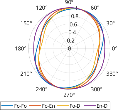
The four curves differ in both shape and direction. The contact between the two pyroxenes, enstatite and diopside, is the roundest, with a minimum at 0.87 of its maximum. It is the least anisotropic boundary population in this rock. The most anisotropic is the forsterite-diopside contact at 0.68, not the forsterite-forsterite boundary at 0.76. What sets the forsterite-forsterite boundary apart is its direction rather than its strength: its long direction is 63 degrees, whereas the other three lie between 75 and 85 degrees.
Characteristic shape
characteristicShape takes every selected boundary segment together with its opposite, sorts those vectors by direction, and lays them end to end. They close into a fabric-equivalent polygon without requiring closed grain outlines. It is often read as an average grain outline, but it is not an observed grain or an arithmetic average grain. It represents the selected boundary-length distribution.
close all
plotopts = {'normalize','linewidth',2,'plain'};

shapeF = characteristicShape(grains.boundary('Fo','Fo'));
plot(shapeF,plotopts{:},'DisplayName','Fo-Fo')
hold on
shapeE = characteristicShape(grains.boundary('En','En'));
plot(shapeE,plotopts{:},'DisplayName','En-En')
shapeEF = characteristicShape(grains.boundary('En','Fo'));
plot(shapeEF,plotopts{:},'DisplayName','En-Fo')
hold off

legend('Location','southoutside','Orientation','horizontal')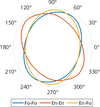
The three polygons are normalized to equal area, so compare their direction and shape rather than their absolute size. The result is a shape2d, which accepts the same shape commands as a grain.
A shape with a mirror line normally has perpendicular longest and shortest fabric axes. The angle between those calipers is then 90 degrees and departs from 90 degrees for a skewed shape. More generally, the angle tests whether the two extrema are perpendicular; it does not by itself prove mirror symmetry. It therefore supplies an asymmetry measure that a single axial ratio cannot.
characteristicCaliperAngle = [...
  angle(shapeF.caliper('longest'),shapeF.caliper('shortest')),...
  angle(shapeE.caliper('longest'),shapeE.caliper('shortest')),...
  angle(shapeEF.caliper('longest'),shapeEF.caliper('shortest'))] ./ degree
characteristicCaliperAngle =
79.3812 79.3216 88.5469The two single-phase shapes both give 79.3 degrees. Each is skewed by about 10.7 degrees, and the two skews run in opposite senses: the outlines are close to mirror images of one another. The mixed forsterite-enstatite shape is nearly symmetric at 88.5 degrees.
These values describe this map. Whether a difference between specimens is larger than sampling variation requires replicate maps, subdivision, or a justified resampling procedure; normalization alone supplies no uncertainty.
Further reading
- R. Panozzo, Two-dimensional analysis of shape-fabric using projections of digitized lines in a plane, Tectonophysics 95 (1983), 279-294, introduces the PAROR construction.
- R. Panozzo, Two-dimensional strain from the orientation of lines in a plane, Journal of Structural Geology 6 (1984), 215-221, develops the SURFOR interpretation.
- R. Heilbronner and S. Barrett, Image Analysis in Earth Sciences: Microstructures and Textures of Earth Materials, Springer, 2014. The chapters on particle and surface fabrics place both methods in a broader image-analysis workflow.
- ISO 13322-1:2014, Particle size analysis - Image analysis methods - Part 1: Static image analysis methods, standardizes static-image measurements including maximum and minimum Feret dimensions.
- ISO 9276-6:2008, Representation of results of particle size analysis - Part 6: Descriptive and quantitative representation of particle shape and morphology, gives shape terminology and emphasizes that most image-based definitions are two-dimensional.
The opening shadow analogy also echoes Edwin A. Abbott's Flatland (1884).
Next
Ellipse Based Shape Parameters compares these projection directions with fitted long axes. Continue to Grain Orientation Parameters to compare shape fabric with orientation variation inside the grains, or to Grain Boundaries when the boundary segments and their crystallographic relations are the subject.
Citing this page.
This page is part of the documentation of
MTEX, a free and open
source MATLAB toolbox for analyzing and modeling crystallographic textures.
It was written by The MTEX Developers and is published at
https://mtex-toolbox.github.io/ProjectionBasedParameters.html.
If you use MTEX, or reuse text or figures from this page, in your research,
please cite
F. Bachmann, R. Hielscher, H. Schaeben: Texture Analysis with MTEX - Free and Open Source Software Toolbox, Solid State Phenomena 160 (2010), 63-68. 10.4028/www.scientific.net/SSP.160.63
BibTeX
@article{bachmann2010mtex,
  author  = {F. Bachmann and R. Hielscher and H. Schaeben},
  title   = {Texture Analysis with MTEX - Free and Open Source Software Toolbox},
  journal = {Solid State Phenomena},
  volume  = {160},
  pages   = {63-68},
  year    = {2010},
  doi     = {10.4028/www.scientific.net/SSP.160.63},
  url     = {https://doi.org/10.4028/www.scientific.net/SSP.160.63}
}
Other papers describing specific MTEX methods are listed under Publications — please cite the one that best fits your application. The MTEX source code is licensed under the GNU General Public License v2.0; the text and figures of this documentation are licensed under CC BY 4.0, which permits reuse — including by automated systems — provided The MTEX Developers and this page are credited.