
MTEX represents a grain as a phase-homogeneous, spatially connected region of EBSD pixels produced by segmentation. For plotting, its outline is a polygon whose fill colour can come from the phase, the mean orientation, or one number computed for that grain.
This page assumes that you have reconstructed grains as described in Grain Reconstruction. If inverse pole figure colours are new to you, read IPF Maps first.
A grain map differs from an EBSD map in one important way. An EBSD map has one colour per measurement, whereas a grain map has one colour per grain. It therefore shows the result of the reconstruction and none of the orientation scatter or measurement-to-measurement noise inside a grain.
% import a demo data set
plottingConvention.default('y↑→x');
mtexdata forsterite silent

% perform grain segmentation and store the grain ids with the map
[grains,ebsd] = calcGrains(ebsd,'minPixel',5);
Phase maps
Called with no second argument, plot colours each grain by its phase. The colour is stored with the crystal symmetry of that phase.
close all
plot(grains)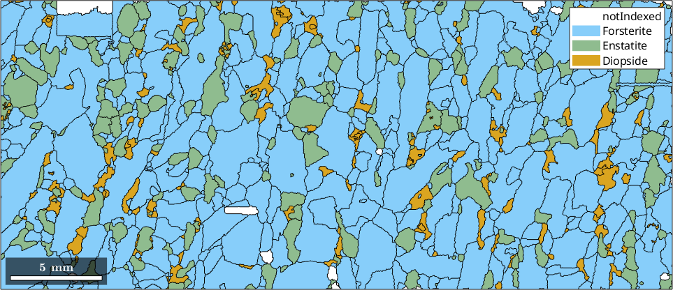
The phase colour can be changed, which is the simplest way to make one phase stand out. Only the forsterite grains change from blue to salmon; the enstatite and diopside colours stay as they were.
grains('Fo').CS.color = "salmon";
plot(grains)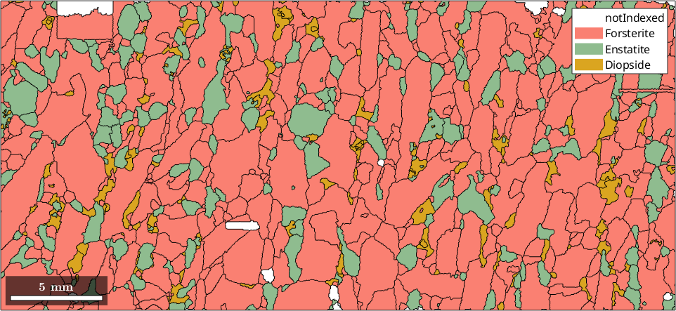
A single grain, or any subset, can instead be given its own colour with 'FaceColor'. Here the largest grain is filled in grey and made partly transparent, so its boundary and the phase map below remain visible.
% detect the largest grain
[~,id] = max(grains.area);

hold on
plot(grains(id),'FaceColor','darkgray','FaceAlpha',0.7)
hold off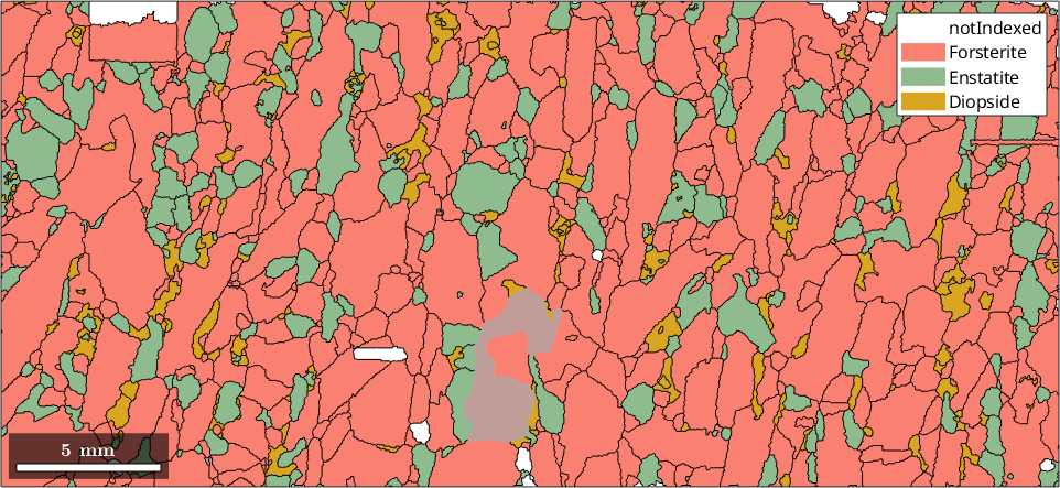
Orientation maps
Passing the mean orientations as the second argument applies an inverse pole figure colour key. The key maps a chosen specimen direction into a crystal direction and assigns that crystal direction a colour. Each phase has its own symmetry and therefore needs its own key, so this is done one phase at a time.
plot(grains('Fo'),grains('Fo').meanOrientation)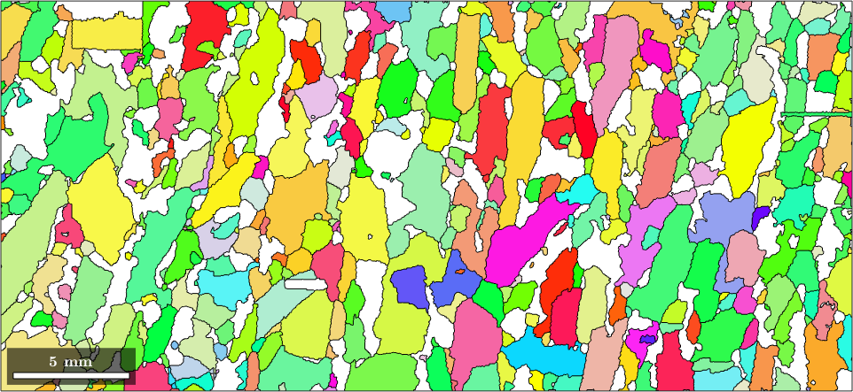
MTEX chooses the specimen z direction for this implicit form and reports the standard colour key in an interactive session. To choose the direction yourself, construct an ipfColorKey and ask it for the colours explicitly.
% a colour key for the forsterite phase
ipfKey = ipfColorKey(grains('Fo'));

% colour by which crystal direction points along specimen x
ipfKey.ipfDirection = vector3d.X;

color = ipfKey.orientation2color(grains('Fo').meanOrientation);
plot(grains('Fo'),color)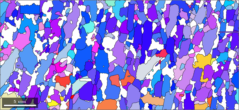
The map has changed completely although the orientations have not. What the colours mean is stored in the key, which should accompany every such map.
figure
plot(ipfKey)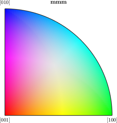
Red is [001], green is [100], and blue is [010]. A red grain in the map above therefore has its [001] axis close to specimen x. In the preceding map, where the implicit key used specimen z, red meant [001] close to z. A colour has no crystallographic meaning without the key that produced it.
Colouring by a grain property
A numeric second argument must contain one value per grain. The colormap turns those values into colours. Here the value is the aspectRatio, the length-to-width ratio of the moment-equivalent ellipse fitted to the grain in this two-dimensional section.
plot(grains,grains.aspectRatio)
mtexColorbar('title','aspect ratio')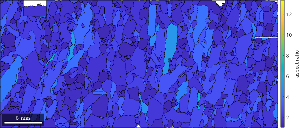
Almost the whole map sits at the bottom of the colour range because a few ribbon-shaped grains reach an aspect ratio of 13 and stretch it. Fixing the range to the interval of interest makes the other grains visible.
setColorRange([1 5])

maxAspectRatio = max(grains.aspectRatio)

numClipped = nnz(grains.aspectRatio > 5)
maxAspectRatio =
13.3424
numClipped =
8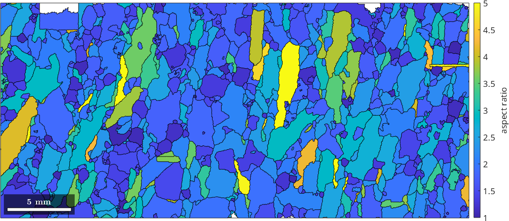
The printed maximum rounds to 13, and the count confirms that eight grains lie above the chosen range. They are no longer distinguishable from one another, so every fixed colour range trades detail in the extremes for contrast through the rest.
These shape values describe the observed section, not the full grain in three dimensions. A grain cut by the map edge is truncated as well, so remove isBoundary grains before calculating shape statistics. The map above keeps them because its purpose is display.
Averaging a measurement property over grains
An EBSD property has one value per measurement and cannot be passed directly to a grain plot. grainMean reduces it to one value per grain. Here it averages the band contrast, a measure of diffraction-pattern quality, over the measurements assigned to each grain.
meanBandContrast = grainMean(ebsd,ebsd.bc,grains);

plot(grains,meanBandContrast)
mtexColorbar('title','mean band contrast')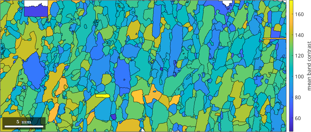
Every polygon now has a uniform fill. The pixel-scale variation of band contrast is gone, and each colour represents the mean for one reconstructed grain. Other reductions, such as @max, can be passed to grainMean when the mean is not the quantity of interest.
Colouring a direction
An angle needs a colormap that closes on itself. The long axis of a grain is an axis rather than a directed vector: 0 and 180 degrees describe the same alignment and must receive the same colour, or the map shows a seam where there is none.
% consider only elongated grains away from the map edge
elongatedGrains = grains(grains.aspectRatio > 1.2 & ~grains.isBoundary);

% angle of the long axis to specimen x, measured about the section normal
omega = angle(vector3d.X,elongatedGrains.longAxis,grains.N);

plot(elongatedGrains,omega ./ degree,'micronbar','off')

% use a cyclic colormap and show its scale
mtexColorMap(colorcet('C2'))
mtexColorbar('title','long-axis angle in degrees')

fractionInBand = mean(omega >= 60*degree & omega <= 105*degree)
fractionInBand =
0.5131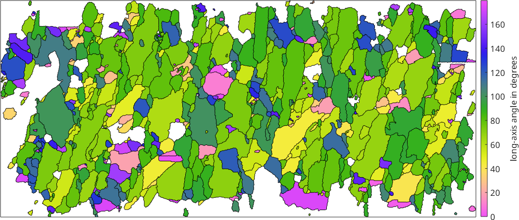
Grains of the same colour are aligned in the same way, and green dominates the map. The printed fraction is close to one half: that many elongated interior grains lie between 60 and 105 degrees from specimen x, which is close to vertical in this plotting convention. The shapes say the same thing at a glance, and this clustering is the visual signature of a shape preferred orientation.
This map is a diagnostic rather than a complete fabric analysis. A quantitative analysis should also decide how grains are weighted and whether phases are compared separately; Ellipse Based Shape Parameters develops those choices.
Colouring by two properties at once
The long axis of a nearly round grain is arbitrary. The previous map gives the same visual weight to a direction that is well defined and to one that is not. A planarColorKey maps one property to hue and a second one to saturation: direction becomes the colour, and aspect ratio controls how strongly that colour is shown.
% hue from a cyclic colormap, periodic because the long axis is an axis
pK = planarColorKey(colorcet('C2'));
pK.periode = pi;

% aspect ratio 1 fades to white, which reads as pale grey beside the outlines
% aspect ratio 3 and above is fully saturated
pK.range2 = [1 3];

prop1 = angle(vector3d.X,grains.longAxis,grains.N);
prop2 = grains.aspectRatio;

colors = pK.property2color(prop1,prop2);
plot(grains,colors)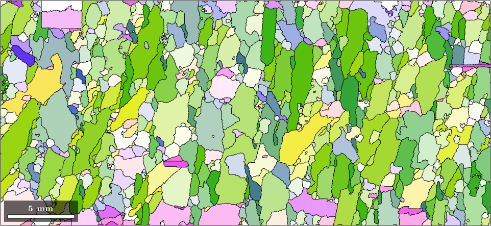
The round grains have faded to nearly white, and only the elongated ones still carry a strong direction colour. The eye is no longer drawn to angles that have little meaning. The key itself can include the observed data range, so the reader can see which combinations occur.
pK.label1 = 'long-axis angle';
pK.label2 = 'aspect ratio';

figure
plot(pK,prop1 ./ degree,prop2)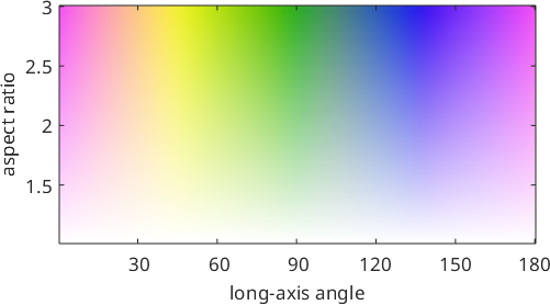
Any pair of scalar grain properties can be combined in this way, provided the hue and saturation assignments are stated with the map.
The measurements inside a grain
A grain map hides the scatter within a grain by construction. To recover it, return to the measurements. The grainId property written into the map by calcGrains ties every measurement to a grain.
% the largest grain
[~,id] = max(grains.area);

% the measurements inside it
ebsdMaxGrain = ebsd(ebsd.grainId == id);

% the shorter form returns the same subset and displays its summary
ebsdMaxGrain = ebsd(grains(id))
ebsdMaxGrain = EBSD (y↑→x)
Phase Orientations Mineral Color Symmetry Crystal reference frame
1 3193 (100%) Forsterite salmon mmm
Properties: bands, bc, bs, error, mad, oldId, grainId
Scan unit : um
X × Y × Z : [16000 → 19350] × [1550 → 6800] × [0 → 0]
Normal vector: (0,0,1)Colouring the measurements with the same key puts them and the grain map on the same scale.
color = ipfKey.orientation2color(ebsdMaxGrain.orientations);

plot(ebsdMaxGrain,color,'micronbar','off')

hold on
plot(grains(id).boundary,'linewidth',2)
hold off

maxDeparture = max(angle(grains(id).meanOrientation,...
  ebsdMaxGrain('indexed').orientations)) ./ degree
maxDeparture =
6.0553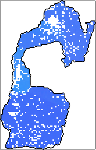
Most of the 3193 measurements in the displayed summary have the same shade of blue. The narrow neck on the left is visibly lighter: its lattice is bent, and the printed maximum departure from the grain mean is 6 degrees. Orientation Parameters measures this variation rather than relying on the colour difference alone.
Before reconstruction, the scattered white pixels had phase notIndexed because their diffraction patterns could not be indexed. The 'alpha' closing absorbed them into the surrounding grain. In the returned map they carry the host phase but still have no orientation to draw. The white bay in the middle is different: the outline is one closed loop that bends around it, so the bay lies outside the grain. A neighbouring forsterite grain fills it and touches this grain from the outside.
Arrows on grains
A direction attached to each grain is often clearer as an arrow. quiver places one at every grain centroid.
% load a single-phase data set
plottingConvention.default('y↓→x');
mtexdata csl silent

[grains,ebsd] = calcGrains(ebsd,'minPixel',5);
grains = smoothBoundary(grains,5);
plot(grains,grains.meanOrientation,'micronbar','off','figSize','large',...
  'region',[50 300 100 250],'ipfDirection',zvector)

% where one representative of the [100] family points in each grain
dir = grains.meanOrientation * Miller(1,0,0,grains.CS);

hold on
quiver(grains,dir,'color','black')
hold off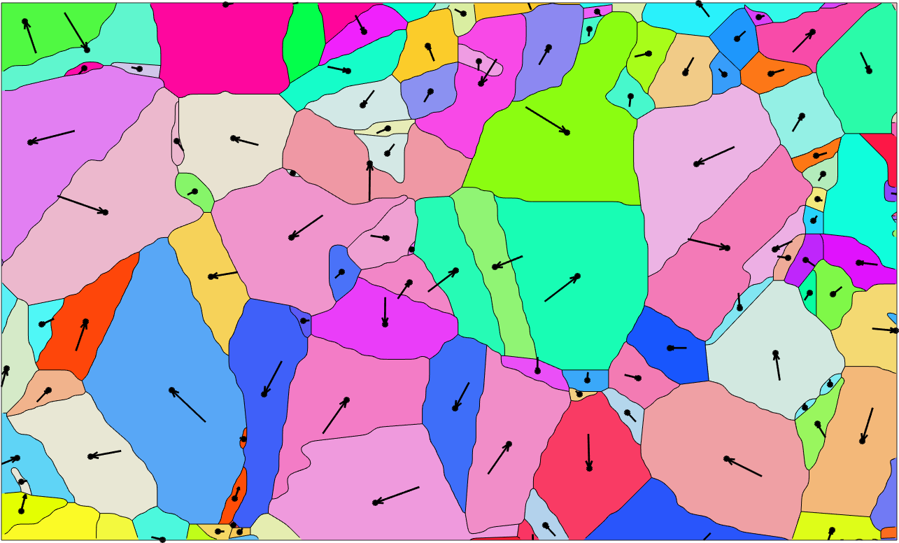
Each arrow is that [100] representative seen from above and is drawn one fifth of its grain's diameter long. In cubic iron, the [100]-type directions are symmetry-equivalent. This example therefore demonstrates the arrow geometry rather than identifying one unique material direction.
Arrow length otherwise carries no information except projection. An arrow appears short when it points steeply out of the section plane. Pass 'noScaling' when the vector magnitudes should set the lengths instead.
An arrow pointing into the screen would be hidden below the map, so MTEX draws it tail first, ending at the grain centre. The small dot marks the centre to which it belongs.
Labelling grains
text writes an arbitrary string at the same centroid. Labelling every grain is unreadable, so this is normally done for a selection. Here the grains larger than 100 pixels are labelled by id.
plot(grains,grains.meanOrientation,'micronbar','off',...
  'region',[50 300 100 250],'ipfDirection',zvector)

bigGrains = grains(grains.numPixel > 100);

text(bigGrains,int2str(bigGrains.id))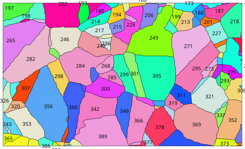
These ids are persistent grain identifiers, not necessarily positions in a subset. Selecting Grains explains the distinction and uses them to recover individual grains and their measurements.
References
- G. Nolze and R. Hielscher, "Orientations - perfectly colored", Journal of Applied Crystallography 49 (2016), 1786-1802, doi:10.1107/S1600576716012942. This paper explains IPF colour continuity, uniqueness, and why the key is part of the interpretation.
- P. Launeau, J.-L. Bouchez and K. Benn, "Shape preferred orientation of object populations: automatic analysis of digitized images", Tectonophysics 180 (1990), 201-211, doi:10.1016/0040-1951(90)90308-U.
- ISO 13067:2020 distinguishes grain measurements made on a two-dimensional polished section from the three-dimensional grain size inferred from them.
Next
Continue with Selecting Grains to build subsets by id, phase, position, property, or orientation. Then Shape Parameters and Orientation Parameters turn the spatial patterns introduced here into quantitative grain measurements.
Citing this page.
This page is part of the documentation of
MTEX, a free and open
source MATLAB toolbox for analyzing and modeling crystallographic textures.
It was written by The MTEX Developers and is published at
https://mtex-toolbox.github.io/GrainSpatialPlots.html.
If you use MTEX, or reuse text or figures from this page, in your research,
please cite
F. Bachmann, R. Hielscher, H. Schaeben: Texture Analysis with MTEX - Free and Open Source Software Toolbox, Solid State Phenomena 160 (2010), 63-68. 10.4028/www.scientific.net/SSP.160.63
BibTeX
@article{bachmann2010mtex,
  author  = {F. Bachmann and R. Hielscher and H. Schaeben},
  title   = {Texture Analysis with MTEX - Free and Open Source Software Toolbox},
  journal = {Solid State Phenomena},
  volume  = {160},
  pages   = {63-68},
  year    = {2010},
  doi     = {10.4028/www.scientific.net/SSP.160.63},
  url     = {https://doi.org/10.4028/www.scientific.net/SSP.160.63}
}
Other papers describing specific MTEX methods are listed under Publications — please cite the one that best fits your application. The MTEX source code is licensed under the GNU General Public License v2.0; the text and figures of this documentation are licensed under CC BY 4.0, which permits reuse — including by automated systems — provided The MTEX Developers and this page are credited.