
An EBSD map is a picture of a list. Each measurement gets one small patch at the position it was taken, and the patch is filled with a colour that represents something measured there. The choice of quantity decides what the picture can show.
This page assumes that the data has been imported and its reference frame has been checked. EBSD maps then follow the same pattern as other MTEX plots: plot(where, what). The first argument selects the measurements and their positions. The optional second argument supplies their colours or the values to colour. This page works through phase, property and orientation maps, then combines two of them.
close all;
plottingConvention.default('y↑→x');
mtexdata forsterite silent
Phase maps
Calling plot without a second argument colours the map by phase. This is the quickest way to see what is in the specimen and where.
plot(ebsd)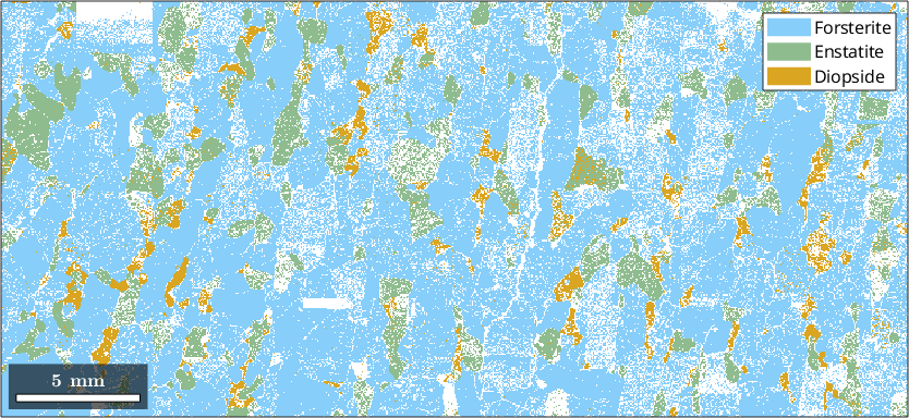
This is a peridotite: a forsterite matrix in light blue, with enstatite in green and smaller diopside grains in orange. The white speckle marks the notIndexed phase. Each point is a recorded measurement whose pattern could not be matched to an indexed phase; it is not a missing position. About a quarter of the map is notIndexed. Many of those measurements crowd along grain boundaries. There the beam interaction volume can meet two crystals at once.
Each phase carries its own colour as an RGB triplet. Leaving this query unterminated displays the triplet assigned to diopside.
ebsd('Diopside').colorans =
0.8549 0.6471 0.1255Any RGB triplet can replace it. The function str2rgb saves you looking one up because it turns a colour name into the triplet.
ebsd('Diopside').color = str2rgb('salmon');

plot(ebsd)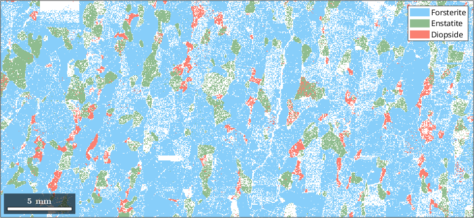
Only diopside has changed from orange to salmon. The phase selection and every measurement remain unchanged.
The notIndexed measurements are white by default, which can read as "nothing here" rather than as data. Giving the phase a colour of its own also puts it in the legend with the indexed phases.
ebsd('notIndexed').color = str2rgb('gray');

plot(ebsd)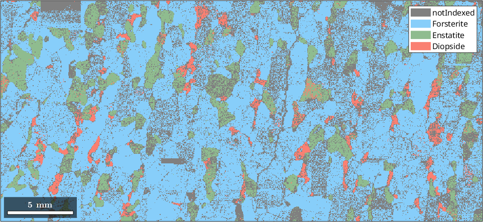
The grey pattern is dense along boundaries and sparse inside grains. It is now visible as information about the specimen rather than as a gap in it.
Maps of a measured property
Any numerical list with one entry per measurement can be the second argument. An EBSD file usually supplies several such properties. The properties here are bands, bc, bs, error, mad and oldId. Band contrast, bc, measures how sharp the diffraction pattern was and is often a useful first property to inspect.
plot(ebsd,ebsd.bc)

colormap gray % make the image grey-scale
mtexColorbar('title','band contrast')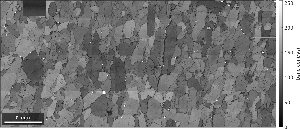
No orientation went into this picture, yet the microstructure is visible. A pattern collected where the beam straddles two crystals is blurred, so many boundaries appear as dark lines. The horizontal banding is an acquisition artefact rather than a feature of the rock. The dark rectangle at the top left is a patch where the patterns were poor throughout.
Maps of the orientation
An orientation has three parameters, so it must be mapped to a colour before it can be shown. A deliberately simple attempt plots only its angle. Here that is the smallest symmetry-equivalent rotation from the identity orientation.
oriAngle = angle(ebsd('Forsterite').orientations)./degree;
plot(ebsd('Forsterite'),oriAngle)
mtexColorbar('title','angle from identity (degree)')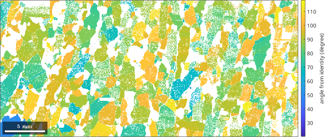
The grains are recognisable, but only just. The angles run from 20° to 118°, while 91% fall between 70° and 110°. Almost the whole map is squeezed into a narrow band of the colour bar. Two grains with the same angle about different axes also receive the same colour. One number cannot separate a three-parameter quantity.
The usual answer is an inverse pole figure colour key. An inverse pole figure fixes a specimen direction and asks which crystal direction lies parallel to it. The key colours the fundamental sector once. It assigns each orientation the colour of its answer.
% define an IPF colour key for forsterite
ipfKey = ipfColorKey(ebsd('Forsterite'));
ipfKey.ipfDirection = vector3d.Z;

% plot its coloured fundamental sector
plot(ipfKey)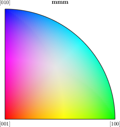
The sector's three corners are the axes of the forsterite cell. This key uses the specimen normal, vector3d.Z, as its fixed direction.
colors = ipfKey.orientation2color(ebsd('Forsterite').orientations);
plot(ebsd('Forsterite'),colors)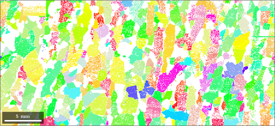
The nearly uniform patches are grains with similar orientations. Red means that the crystallographic \(c\) axis is near the specimen normal. Green marks the \(a\) axis and blue the \(b\) axis. Intermediate directions are blended according to the key.
One IPF map still does not encode the full orientation because it tracks only one fixed specimen direction. The colour is a choice, not a measurement, and another key can make the same data look different. IPF Maps explains those choices. Advanced Plotting covers keys that answer questions other than "which direction points where".
Two maps in one figure
Different maps combine by drawing subsets of the data on top of each other. The option 'faceAlpha' makes the upper layer transparent so that the lower one remains visible.
plot(ebsd,ebsd.bc)
mtexColorMap black2white

hold on
plot(ebsd('Forsterite'),colors,'faceAlpha',0.5)
hold off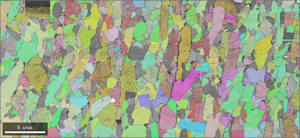
The band contrast supplies the boundaries and the surface detail, the orientation colours distinguish the grains, and neither layer hides the other.
Further reading
Schwartz et al. (eds.), Electron Backscatter Diffraction in Materials Science, 2nd ed. (2009). This textbook gives the experimental and analytical background to EBSD measurements and orientation imaging.
Nolze and Hielscher, Orientations - perfectly colored, J. Appl. Cryst. 49 (2016), 1786-1802. This paper explains the trade-offs and unavoidable ambiguities of inverse pole figure colour keys.
Citing this page.
This page is part of the documentation of
MTEX, a free and open
source MATLAB toolbox for analyzing and modeling crystallographic textures.
It was written by The MTEX Developers and is published at
https://mtex-toolbox.github.io/EBSDPlotting.html.
If you use MTEX, or reuse text or figures from this page, in your research,
please cite
F. Bachmann, R. Hielscher, H. Schaeben: Texture Analysis with MTEX - Free and Open Source Software Toolbox, Solid State Phenomena 160 (2010), 63-68. 10.4028/www.scientific.net/SSP.160.63
BibTeX
@article{bachmann2010mtex,
  author  = {F. Bachmann and R. Hielscher and H. Schaeben},
  title   = {Texture Analysis with MTEX - Free and Open Source Software Toolbox},
  journal = {Solid State Phenomena},
  volume  = {160},
  pages   = {63-68},
  year    = {2010},
  doi     = {10.4028/www.scientific.net/SSP.160.63},
  url     = {https://doi.org/10.4028/www.scientific.net/SSP.160.63}
}
Other papers describing specific MTEX methods are listed under Publications — please cite the one that best fits your application. The MTEX source code is licensed under the GNU General Public License v2.0; the text and figures of this documentation are licensed under CC BY 4.0, which permits reuse — including by automated systems — provided The MTEX Developers and this page are credited.