
A sphere cannot be flattened without distorting something, and which property is given up decides what a figure may be used for. A spherical projection maps directions from the sphere to a plane. MTEX accepts seven of them plus a three-dimensional view, and this page works through the four that come up in texture analysis: equal area, equal distance, equal angle, and plain. They are available on every spherical plot: pole figures, inverse pole figures, ODF sections.
Make three choices in order. First decide whether opposite directions must remain distinct. Then decide how the reference frame is laid out on screen. Finally choose which geometric property the projection should preserve. Exporting Figures preserves the resulting picture, but export settings do not identify an unstated projection.
plottingConvention.default('y↑→x');

cs = crystalSymmetry('321');
odf = fibreODF(Miller(1,1,0,cs),zvector);
Choosing a hemisphere
With triclinic specimen symmetry the two hemispheres of a pole figure differ. MTEX therefore draws both by default, with the upper hemisphere on the left and the lower hemisphere on the right. Here, upper means the half towards the plotting convention's out-of-screen direction. Lower means the opposite half. The 'minmax' option labels the extrema; it does not choose the hemispheres.
plotPDF(odf,Miller(1,1,0,cs),'minmax')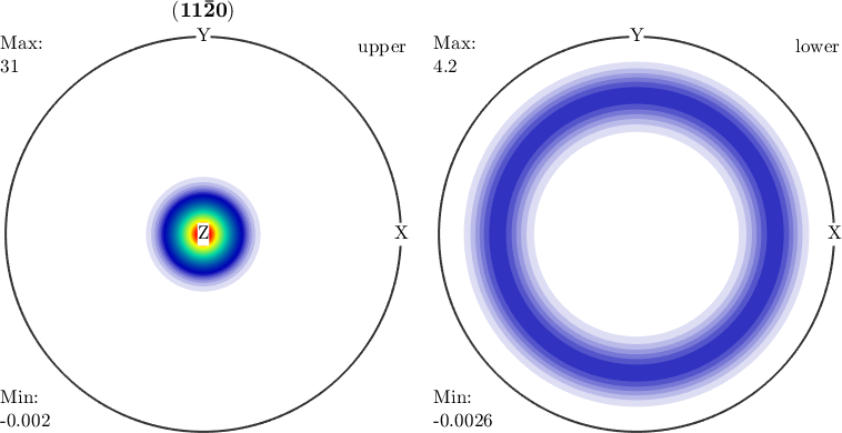
The two panels differ because triclinic specimen symmetry does not identify their directions. The labels report the largest and smallest plotted values; they do not alter either panel.
The 'upper' and 'lower' flags ask for one hemisphere alone. Here only the lower hemisphere remains.
plotPDF(odf,Miller(1,1,0,cs),'lower')
mtexColorbar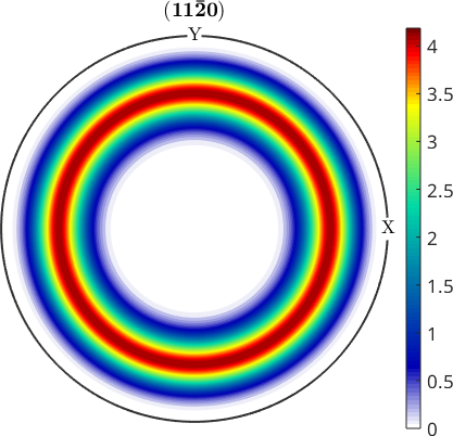
The remaining panel is the lower half selected by the current plotting convention. Hemisphere selection therefore has to be settled before the convention is changed.
A measured pole figure is neither single hemisphere. Friedel's law makes ordinary diffraction blind to the difference between a direction and its opposite. A measurement is therefore a superposition of the two hemispheres. The 'antipodal' flag identifies each direction with its opposite and produces this view. Any figure compared with measured pole-figure data must use it.
plotPDF(odf,Miller(1,1,0,cs),'antipodal')
mtexColorbar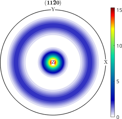
Alignment on screen
A reference frame is the coordinate system in which data are expressed. It has an identity, a basis, and a default plotting convention. The plotting convention says which axis points east and which points out of the screen. Axes Alignment develops this distinction. A convention passed to one plot overrides only that figure's layout. It does not change the data or their reference frame.
how2plot = plottingConvention('z↑→y');

plotPDF(odf,Miller(1,0,0,cs),'antipodal',how2plot)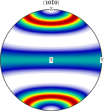
A pole figure lives on the specimen sphere, so these are specimen axes: specimen \(z\) points up and specimen \(y\) points to the right, with \(x\) at the centre. Only the screen arrangement changed; the ODF and its pole densities did not.
Equal area, the default
The equal-area or Schmidt projection preserves area. A pole figure is a density per unit area. This projection therefore preserves the visual impression of how much of the sphere a feature covers, which is why it is the default. The names 'earea' and 'schmidt' request it explicitly.
plotPDF(odf,Miller(1,0,0,cs),'antipodal','projection','earea')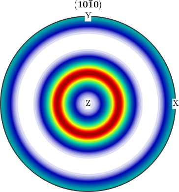
Use this projection when the area occupied by a density feature matters. Shape and radial distance are still distorted, because preserving area does not preserve every other geometric property.
Equal distance and equal angle
The equal-distance projection makes radial distance proportional to the angular distance from the centre. An angle from the central direction can therefore be read with a ruler. The stereographic, or equal-angle, projection preserves angles between intersecting curves, including great circles. This property supports geometric crystallographic constructions.
Compare the three projections side by side using the same crystal directions from a cubic symmetry. Their shared 15 degree grid provides the scale for the comparison.
cs = crystalSymmetry('m-3m');
newMtexFigure('layout',[1,3])
plotHKL(cs,'projection','earea','upper','grid_res',15*degree,...
  'backgroundColor','w')
mtexTitle('equal area')
nextAxis
plotHKL(cs,'projection','edist','upper','grid_res',15*degree,...
  'backgroundColor','w')
mtexTitle('equal distance')
nextAxis
plotHKL(cs,'projection','eangle','upper','grid_res',15*degree,...
  'backgroundColor','w')
mtexTitle('equal angle')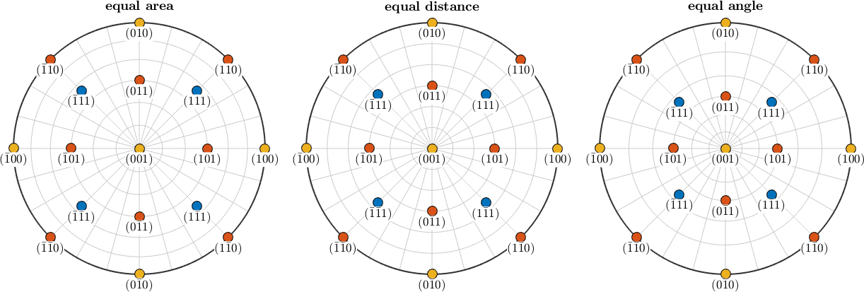
The same directions occupy visibly different positions in the three panels. Compare the grid circles from the centre towards the rim. Equal-distance spacing stays constant, equal-area spacing crowds towards the rim, and equal-angle spacing spreads. A figure without its projection named is not fully specified. Mixing projections in one comparison creates a difference that can be difficult to detect. Use equal distance for radial angular measurements and equal angle for local angular constructions.
Plain projection
The 'plain' option is not a spherical projection. It plots the polar angles theta and rho as rectangular coordinates, measured in degrees. Both angles are easy to read from the axes. Areas are meaningless because the poles of the sphere become complete edges. This is the traditional presentation for ODF sections.
plot(SantaFe,'alpha','sections',18,...
  'projection','plain','contourf','FontSize',10,'silent')
mtexColorMap white2black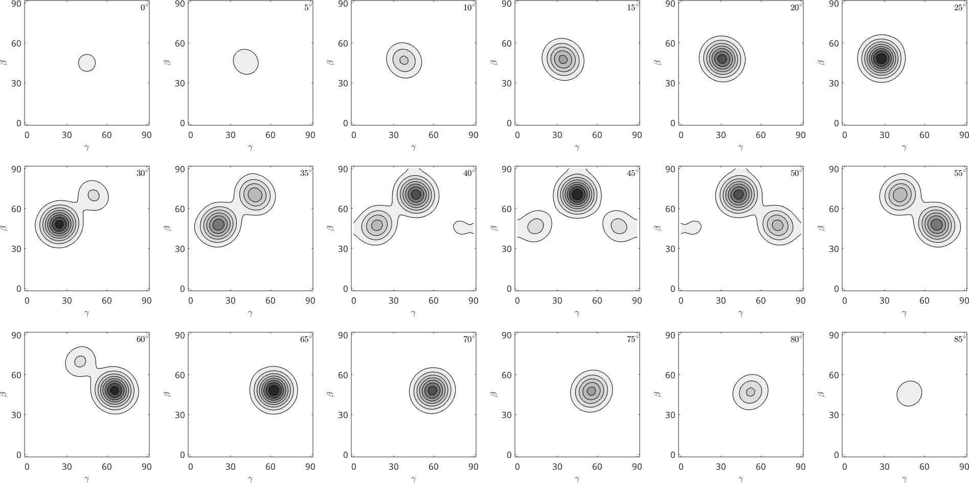
The rectangular axes make section coordinates easy to locate. The apparent size of a contour region must not be interpreted as spherical area, because the mapping stretches the sphere into a rectangle.
Three dimensions
A three-dimensional plot avoids flattening the sphere and can be rotated freely. At any moment, however, half of the data lies behind the visible half. The 'grid' flag adds a spherical grid, and 'grid_res' sets its angular spacing.
how2plot = plottingConvention;
how2plot.east = vector3d(9,3,3);
how2plot.outOfScreen = vector3d(6,10,9);

close all
plotPDF(odf,Miller(1,1,0,odf.CS),'3d',how2plot,...
  'grid','grid_res',10*degree,'noTitle')
mtexColorMap LaboTeX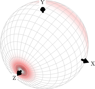
The oblique convention exposes the sphere's depth and makes the grid's curvature visible. Use this plot when the question is where a feature lies on the sphere. Avoid it when the question is how much area the feature occupies, because a perspective view does not preserve area.
References
- H.-J. Bunge, Texture Analysis in Materials Science: Mathematical Methods, Butterworths, English ed., 1982, develops pole figures and the spherical projections used in texture analysis.
- J. P. Snyder, Map Projections: A Working Manual, U.S. Geological Survey Professional Paper 1395, 1987, derives the area, distance, and angle properties that distinguish these projections.
- The International Union of Crystallography, Friedel's law, explains when diffraction intensities from opposite directions are equal and when they may differ.
Next
Once the projection is fixed, continue with Legends to name the plotted objects and place their identifying symbols without covering the data.
Citing this page.
This page is part of the documentation of
MTEX, a free and open
source MATLAB toolbox for analyzing and modeling crystallographic textures.
It was written by The MTEX Developers and is published at
https://mtex-toolbox.github.io/SphericalProjections.html.
If you use MTEX, or reuse text or figures from this page, in your research,
please cite
F. Bachmann, R. Hielscher, H. Schaeben: Texture Analysis with MTEX - Free and Open Source Software Toolbox, Solid State Phenomena 160 (2010), 63-68. 10.4028/www.scientific.net/SSP.160.63
BibTeX
@article{bachmann2010mtex,
  author  = {F. Bachmann and R. Hielscher and H. Schaeben},
  title   = {Texture Analysis with MTEX - Free and Open Source Software Toolbox},
  journal = {Solid State Phenomena},
  volume  = {160},
  pages   = {63-68},
  year    = {2010},
  doi     = {10.4028/www.scientific.net/SSP.160.63},
  url     = {https://doi.org/10.4028/www.scientific.net/SSP.160.63}
}
Other papers describing specific MTEX methods are listed under Publications — please cite the one that best fits your application. The MTEX source code is licensed under the GNU General Public License v2.0; the text and figures of this documentation are licensed under CC BY 4.0, which permits reuse — including by automated systems — provided The MTEX Developers and this page are credited.