
A map shows an orientation gradient as a change of colour, but colour is difficult to read quantitatively. A line profile turns the same change into a curve against distance. A steady lattice rotation then appears as a slope, whereas an abrupt change appears as a jump.
This page assumes the grain segmentation introduced in Grain Reconstruction and the inverse pole figures introduced in Orientation Plots. Check the specimen reference frame as described in Reference Frame before interpreting a profile direction.
The example uses the forsterite map. Its plotting convention draws specimen Y upward and specimen X to the right.
close all;
plottingConvention.default('y↑→x');
mtexdata forsterite silent
Select a grain with a large orientation spread
A grain is a phase-homogeneous, spatially connected region of EBSD pixels produced by segmentation. Reconstruct the grains with a 15° boundary threshold, then select the grain with the largest grain orientation spread (GOS). GOS is the mean angular deviation from the grain's mean orientation; Orientation Parameters explains it in detail.
[grains,ebsd] = calcGrains(ebsd,'minPixel',5,'angle',15*degree);
[~,id] = max(grains.GOS);
grainSelected = grains(id)

% plot the selected grain with its measured orientations
close all;
plot(grainSelected.boundary,'lineWidth',2);
hold on;
plot(ebsd(grainSelected),ebsd(grainSelected).orientations,...
  'ipfDirection',zvector);
hold off;
grainSelected = grain2d (y↑→x)
Phase Grains Pixels Mineral Symmetry Color
1 1 2614 Forsterite mmm LightSkyBlue
boundary segments: 418 (18506 µm)
inner boundary segments: 54 (2328 µm)
triple points: 17
Id Phase Pixels meanRotation GOS
431 1 2614 (153°,109°,246°) 0.17005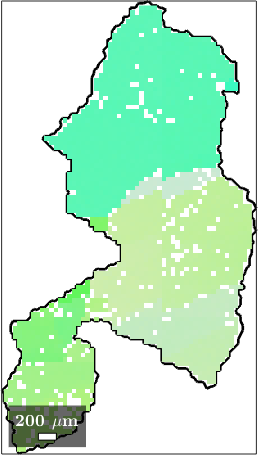
Its spread is 9.7°, which is large for a single grain. The orientation colours change visibly from one end to the other, so this grain is a useful place to compare gradual rotation with abrupt jumps.
Draw and extract the profile
Specify the segment by its two endpoint coordinates and draw it on the map. In interactive work, lineSec = ginput(2) lets you click those endpoints. Fixed coordinates keep this published example executable. They use the same units as the map.
lineSec = [18826 6438; 18089 10599];
line(lineSec(:,1),lineSec(:,2),'lineWidth',2);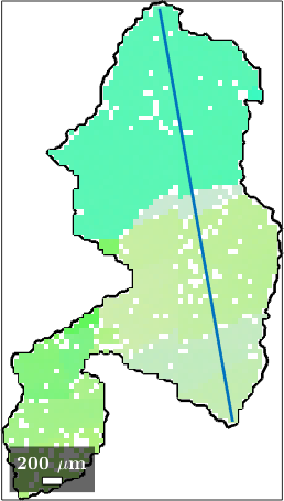
spatialProfile returns the measurements near the segment in traversal order. Its second output is their projected distance from the first endpoint. The object summary shows that this profile contains 86 measurements.
[ebsdLine,profileDist] = spatialProfile(ebsd(grainSelected),lineSec);
ebsdLine
ebsdLine = EBSD (y↑→x)
Phase Orientations Mineral Color Symmetry Crystal reference frame
1 86 (100%) Forsterite LightSkyBlue mmm
Properties: bands, bc, bs, error, mad, oldId, grainId
Scan unit : um
X × Y × Z : [18100 → 18800] × [6450 → 10600] × [0 → 0]
Normal vector: (0,0,1)Compare point-to-origin and point-to-point changes
The point-to-origin curve compares every orientation with the first one on the line. It shows the accumulated change, but its value depends on that chosen reference point. The point-to-point curve compares consecutive measurements and exposes local jumps.
oriLine = ebsdLine.orientations;
toOrigin = angle(oriLine(1),oriLine) ./ degree;
pointToPoint = angle(oriLine(1:end-1),oriLine(2:end)) ./ degree;
midDist = 0.5 * (profileDist(1:end-1) + profileDist(2:end));

close all;
plot(profileDist,toOrigin,'lineWidth',1.5);
hold on;
plot(midDist,pointToPoint,'lineWidth',1.5);
hold off;

xlabel(['distance along profile (' ebsdLine.scanUnit ')']);
ylabel('misorientation angle in degree');
legend('point-to-origin','point-to-point');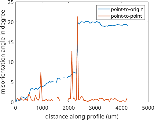
The point-to-origin curve climbs steadily to about 7° over a little more than half the line, then jumps to 20° and stays nearly flat. The point-to-point curve says the same thing locally. It remains at a few tenths of a degree almost everywhere, which reveals the steady bending, but contains three isolated spikes; the largest is 21°.
The point-to-point values are angular increments, not spatial gradients. Divide them by the corresponding distance increments to obtain an angle per unit length. Small increments are also sensitive to measurement noise and to the scan step size, so compare profiles acquired at a common spatial scale.
A jump of 21° inside one grain deserves attention because the grains were reconstructed with a threshold of 15°. It is not a contradiction. Segmentation joins neighboring pixels whose disorientation is below the threshold, and the two parts of this grain are connected by a path that goes around the jump. The three gaps trace pixels that were notIndexed before reconstruction. They were absorbed into the grain footprint, but calcGrains did not invent orientations for them.
Track the full orientations in inverse pole figures
A misorientation angle discards the axis about which the crystal turns. Plotting the orientations in inverse pole figures retains that directional information. Colouring the markers by distance retains their order along the line.
close;
plotIPDF(oriLine,[xvector,yvector,zvector],...
  'property',profileDist,'MarkerSize',20,'antipodal');
mtexColorbar('title',['distance along profile (' ebsdLine.scanUnit ')']);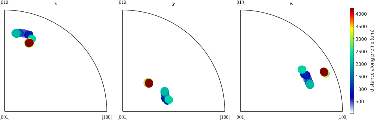
Every panel holds the same two groups. The measurements before the jump, dark blue through teal, trace a short chain rather than a point: their directions spread by up to 7° in the x and z panels and 4° in y, which is the gradual bending seen in the curves above. The measurements after the jump are all yellow and lie within about 1° of each other, so they merge into one marker.
How far apart the two groups appear depends on the specimen direction. Their means are 17° and 18° apart in the y and z panels, but only 8° apart in x, where the yellow marker touches the end of the chain. A jump that is unmistakable in one inverse pole figure can be inconspicuous in another, which is why all three are plotted. Inspecting both angle and direction helps distinguish a coherent lattice rotation from isolated indexing artefacts.
Further reading
- S. Van Boxel, M. Seefeldt, B. Verlinden and P. Van Houtte, Visualization of grain subdivision by analysing the misorientations within a grain using electron backscatter diffraction, Journal of Microscopy 218 (2005), 104-114, compares point-to-point changes with grain-scale misorientation and shows why the misorientation axis matters.
- M. Kamaya, Correction of step size dependency in local misorientation obtained by EBSD measurements: Introducing equidistant local misorientation, Ultramicroscopy 259 (2024), 113928, examines how point spacing changes local misorientation.
- A. J. Schwartz, M. Kumar, B. L. Adams and D. P. Field, editors, Electron Backscatter Diffraction in Materials Science, second edition, Springer, 2009, provides the wider experimental and analytical background to EBSD maps.
- ISO 24173:2024, Microbeam analysis - Guidelines for orientation measurement using electron backscatter diffraction, covers reliable and reproducible orientation measurements, including acquisition and calibration.
Next
A profile answers a directional, path-dependent question. For a local map of neighboring orientation changes, continue with KAM. For each point's deviation from its grain mean, use Mis2Mean / GROD. Denoising explains how to reduce orientation noise before interpreting changes of only a few tenths of a degree.
Citing this page.
This page is part of the documentation of
MTEX, a free and open
source MATLAB toolbox for analyzing and modeling crystallographic textures.
It was written by The MTEX Developers and is published at
https://mtex-toolbox.github.io/EBSDProfile.html.
If you use MTEX, or reuse text or figures from this page, in your research,
please cite
F. Bachmann, R. Hielscher, H. Schaeben: Texture Analysis with MTEX - Free and Open Source Software Toolbox, Solid State Phenomena 160 (2010), 63-68. 10.4028/www.scientific.net/SSP.160.63
BibTeX
@article{bachmann2010mtex,
  author  = {F. Bachmann and R. Hielscher and H. Schaeben},
  title   = {Texture Analysis with MTEX - Free and Open Source Software Toolbox},
  journal = {Solid State Phenomena},
  volume  = {160},
  pages   = {63-68},
  year    = {2010},
  doi     = {10.4028/www.scientific.net/SSP.160.63},
  url     = {https://doi.org/10.4028/www.scientific.net/SSP.160.63}
}
Other papers describing specific MTEX methods are listed under Publications — please cite the one that best fits your application. The MTEX source code is licensed under the GNU General Public License v2.0; the text and figures of this documentation are licensed under CC BY 4.0, which permits reuse — including by automated systems — provided The MTEX Developers and this page are credited.