
A colour key that covers the full orientation range can hide changes of only a few degrees. A sharp colour key spends more of its colour range on the small orientation range occupied by the data.
Sharpening changes only the display. It does not change the measured orientations, improve their angular precision, or denoise the map. IPF Maps introduces inverse pole figure colour keys. The examples below also assume that the data's reference frame has already been checked.
The first example is a calcite scan stored on a 301-by-151 rectangular grid, or 45451 grid positions. It contains 20119 indexed calcite measurements, 32 notIndexed measurements, and 25300 padding positions with no measurement. Padding and the notIndexed phase are not the same.
plottingConvention.default('y↓→x');
mtexdata sharp

ipfKey = ipfColorKey(ebsd)

plot(ebsd,ipfKey.orientation2color(ebsd.orientations))
xlim(ebsd.extent(1:2)),ylim(ebsd.extent(3:4))
ebsd = EBSDsquare (y↓→x, y↓→x)
Phase Orientations Mineral Color Symmetry Crystal reference frame
0 32 (0.07%) notIndexed none
1 20119 (44%) calcite LightSkyBlue -3m1 X||a*, Y||b, Z||c
Properties: oldId
Scan unit : um
X × Y × Z : [0 → 200] × [-100 → 0] × [0 → 0]
Normal vector: (0,0,1)
Square grid :301 × 151
ipfKey = ipfColorKey (calcite → y↓→x)
ipfDirection : (0,0,1)
direction key: HSVDirectionKey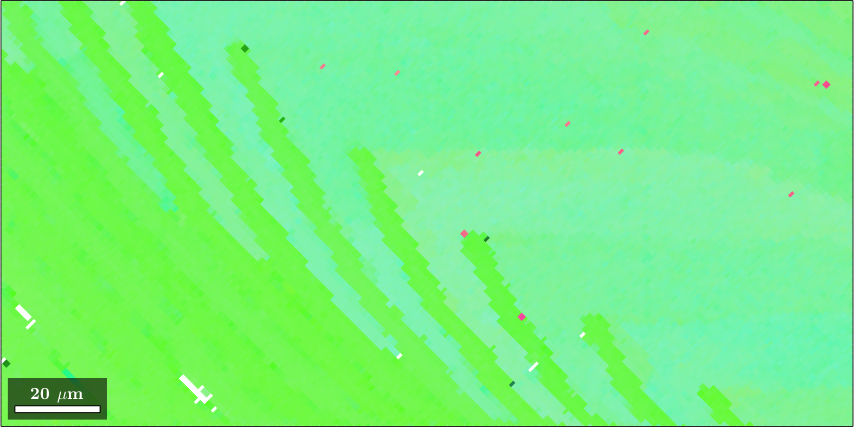
The printed summary distinguishes the measurements from the rectangular grid size. The key display states which specimen direction it colours. The map is nearly one shade of green. Faint diagonal bands and a few red pixels are visible, but the default key cannot resolve most differences.
An IPF colour represents one selected specimen direction, not a complete orientation. Equal colours therefore do not prove equal orientations.
Colouring by one number
The most direct approach is to colour one scalar quantity. Here r is the specimen direction \((1,0,1)\). Applying the inverse orientations maps it into crystal directions h, which are then reduced by crystal symmetry to the fundamental sector.
r = vector3d(1,0,1);

% map the specimen direction into the crystal frame
h = ebsd.orientations .\ r;
h = project2FundamentalRegion(h);

% use its azimuth in degrees as the colour value
color = h.rho ./ degree;

plotIPDF(ebsd.orientations,r,'property',color,...
  'MarkerSize',3,'grid','points','all')
mtexColorbar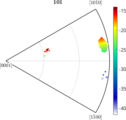
The azimuth has a median of -22 degrees. The central 98% of the measurements lie between -24 and -18 degrees, while a thin tail reaches -42 degrees. That tail sets the automatic colour range and leaves little contrast for the main cloud.
Restricting the range to the main cloud restores the contrast. Values outside it are clipped to an end colour, so both ends are changed to purple to mark them explicitly as outliers.
setColorRange([-25 -14]);

% mark values outside the displayed range
cmap = colormap;
cmap(end,:) = [1 0 1];
cmap(1,:) = [1 0 1];
colormap(cmap)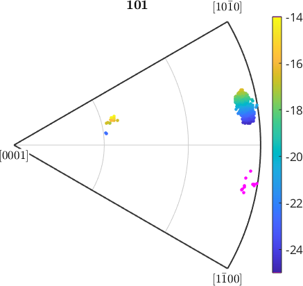
The main cloud now spans the colour bar, while the separated tail is purple. Azimuth is a circular coordinate, so this scalar view is useful only while the cluster stays away from its wrap-around discontinuity.
The same values and colour range can now be drawn at their map positions.
plot(ebsd,color)
xlim(ebsd.extent(1:2)),ylim(ebsd.extent(3:4))

setColorRange([-25 -14]);

cmap = colormap;
cmap(end,:) = [1 0 1];
cmap(1,:) = [1 0 1];
colormap(cmap)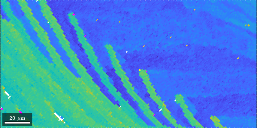
What was one flat hue is now a map of sharp diagonal lamellae. The purple pixels scattered over the map belong to the tail of the distribution. This view displays azimuth only and discards the other orientation information.
Sharpening the inverse pole figure key
A sharp IPF key keeps the two-dimensional inverse pole figure representation. Two settings place its steep colour transition around the data: the mean maps to the white centre, and maxAngle sets the angular distance at which the selected IPF direction reaches full colour.
This example deliberately uses calcite's proper group, 321, instead of its Laue group, -3m. That changes which crystal directions are treated as equivalent; it is a symmetry choice, not part of sharpening. Use the proper group only when that distinction is intended, as explained in Laue or enantiomorphic symmetry groups.
ipfKey = ipfHSVKey(ebsd.CS.properGroup);

% map the robust mean orientation to the white centre
meanOri = mean(ebsd.orientations,'robust');
ipfKey.ipfDirection = meanOri * ipfKey.whiteCenter;

close all;
plot(ebsd,ipfKey.orientation2color(ebsd.orientations))
xlim(ebsd.extent(1:2)),ylim(ebsd.extent(3:4))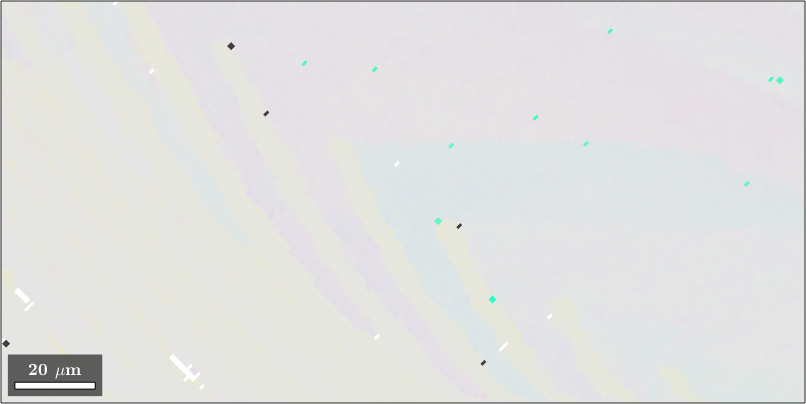
Almost everything is grey because most selected IPF directions lie near the white centre. The few distant measurements appear dark. Half the measurements are within 2.6 degrees in disorientation from the robust mean, which confirms that the orientation range itself is small.
ipfKey.maxAngle = 7.5*degree;
plot(ebsd,ipfKey.orientation2color(ebsd.orientations))
xlim(ebsd.extent(1:2)),ylim(ebsd.extent(3:4))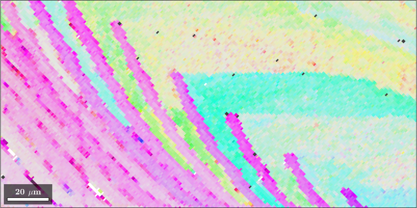
White still represents the mean. A selected IPF direction becomes more saturated as it moves away from the white centre, and it saturates at maxAngle. A smaller value gives more contrast but also makes more measurements indistinguishable at full saturation, so it is worth varying this setting.
Drawing the key and ten sampled orientations shows where the contrast was placed.
plot(ipfKey,'resolution',0.25*degree)

hold on
plotIPDF(ebsd('indexed').orientations,ipfKey.ipfDirection,'points',10,...
  'MarkerSize',1,'MarkerFaceColor','w','MarkerEdgeColor','w')
hold off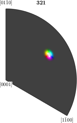
The ten orientations form a tight cloud around the white centre. The transition from white to full colour occurs in the same small region. This is the whole trick: the steep part of the key lies where the data is.
The axis-angle colour key
The axisAngleColorKey answers a different question. It colours the deviation from a reference orientation: hue represents the disorientation axis and saturation represents the disorientation angle. This uses all three parameters of the deviation rather than one IPF direction.
A useful reference is each grain's mean orientation. A grain is a phase-homogeneous, spatially connected region of EBSD measurements produced by segmentation. Grain Reconstruction explains that step.
[grains,ebsd] = calcGrains(ebsd,'angle',1.5*degree,'minPixel',5);
grains = smoothBoundary(grains,5);
The segmentation threshold is 1.5 degrees, far below the commonly used 10 degrees. It separates the small changes that this page is intended to reveal. The resulting colours therefore depend on both this segmentation and the grain means; colours in different grains are not absolute orientation colours.
ipfKey = axisAngleColorKey(ebsd);
indexed = ebsd('indexed');

% use the original grain mean as the reference for each measurement
ipfKey.oriRef = grains.meanOrientation(indexed.grainId);

% keep the raw 80th percentile as one scale for both maps
rawDeviation = angle(indexed.orientations,ipfKey.oriRef);
ipfKey.maxAngle = quantile(rawDeviation,0.8);

plot(indexed,ipfKey.orientation2color(indexed.orientations))

hold on
plot(grains.boundary,'lineWidth',4,'LineColor','white')
plot(grains.boundary,'lineWidth',2,'LineColor','black')
hold off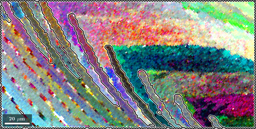
Within each grain, similar hues identify a common disorientation axis and stronger saturation identifies a larger angle from the original grain mean. Pixel-scale speckle is superposed on extended colour gradients. The outlined grains are the segmentation used to define the references.
This sensitive view also shows what a denoising filter changes. The filter itself is explained in Denoising Orientation Maps, and the colour construction follows Thomsen et al. (2017).
F = l1TVFilter;
F.alpha = 1.25;
ebsdS = smooth(ebsd,F,'fill',grains);
indexedS = ebsdS('indexed');

% compare with the same references and saturation scale
ipfKey.oriRef = grains.meanOrientation(indexedS.grainId);

plot(indexedS,ipfKey.orientation2color(indexedS.orientations))

hold on
plot(grains.boundary,'lineWidth',4,'LineColor','white')
plot(grains.boundary,'lineWidth',2,'LineColor','black')
hold off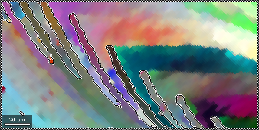
Most pixel-scale speckle has gone, while the extended gradients within the grains remain. The grain reconstruction, reference orientations, boundaries, and saturation scale are unchanged between the two maps. Sharpening makes this comparison visible; it does not by itself prove that the denoised orientations are more accurate.
Orientation gradients inside one grain
The last application is the largest grain in the forsterite map. Its specimen frame needs a different plotting convention, which is stated explicitly.
plottingConvention.default('y↑→x');
mtexdata forsterite silent

% reconstruct grains and select the largest one
[grains,ebsd] = calcGrains(ebsd);
[~,ind] = max(grains.numPixel);
largeGrains = grains(ind);
ebsd = ebsd(largeGrains);
With the ordinary key this grain appears almost one colour, as a grain often does at this scale. A grain is not required to be orientation uniform: segmentation only keeps neighbouring measurements together while their differences remain below the chosen boundary criterion.
close all
plot(largeGrains.boundary,'linewidth',2)
hold on
plot(ebsd,ebsd.orientations)
hold off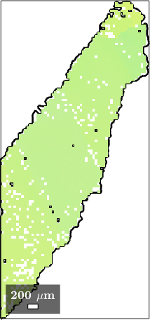
Centring a sharp key on this grain's mean reveals the variation that the ordinary key compressed.
plot(largeGrains.boundary,'linewidth',2)
hold on
ipfKey = ipfHSVKey(ebsd);
ipfKey.ipfDirection = mean(ebsd.orientations) * ipfKey.whiteCenter;
ipfKey.maxAngle = 10*degree;
plot(ebsd,ipfKey.orientation2color(ebsd.orientations))
hold off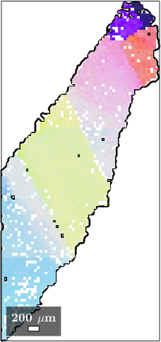
At this scale the grain is not uniform at all. It falls into large domains whose selected IPF directions are a few degrees apart, with gradual transitions between them. The single colour of the previous figure hid every one of those domains.
This image locates the variation but does not quantify the complete orientation deviation. Grain Reference Orientation Deviation computes the full angle and axis relative to a grain mean.
Choosing a sharp view
Use a clipped scalar map when one coordinate has a direct interpretation and its circular discontinuity is safely outside the data. Use a sharp IPF key when variation of one specimen direction is the question. Use an axis-angle key when the full deviation from a chosen reference matters.
In every case, state the centre, range, symmetry, and reference orientations. Without them, colours from different maps are not quantitatively comparable.
Further reading
- G. Nolze and R. Hielscher, Orientations - perfectly colored, Journal of Applied Crystallography 49, 1786-1802, 2016, explains the continuity and uniqueness trade-offs of IPF colour keys.
- K. Thomsen, K. Mehnert, P. W. Trimby, and A. Gholinia, Quaternion-based disorientation coloring of orientation maps, Ultramicroscopy 182, 62-67, 2017, develops the grain-relative disorientation colouring used by the axis-angle example.
Next
Advanced Color Keys compares other orientation encodings. Denoising Orientation Maps treats the filter used above, while Kernel Average Misorientation and Grain Reference Orientation Deviation quantify local and grain-relative orientation changes.
Citing this page.
This page is part of the documentation of
MTEX, a free and open
source MATLAB toolbox for analyzing and modeling crystallographic textures.
It was written by The MTEX Developers and is published at
https://mtex-toolbox.github.io/EBSDSharpPlot.html.
If you use MTEX, or reuse text or figures from this page, in your research,
please cite
F. Bachmann, R. Hielscher, H. Schaeben: Texture Analysis with MTEX - Free and Open Source Software Toolbox, Solid State Phenomena 160 (2010), 63-68. 10.4028/www.scientific.net/SSP.160.63
BibTeX
@article{bachmann2010mtex,
  author  = {F. Bachmann and R. Hielscher and H. Schaeben},
  title   = {Texture Analysis with MTEX - Free and Open Source Software Toolbox},
  journal = {Solid State Phenomena},
  volume  = {160},
  pages   = {63-68},
  year    = {2010},
  doi     = {10.4028/www.scientific.net/SSP.160.63},
  url     = {https://doi.org/10.4028/www.scientific.net/SSP.160.63}
}
Other papers describing specific MTEX methods are listed under Publications — please cite the one that best fits your application. The MTEX source code is licensed under the GNU General Public License v2.0; the text and figures of this documentation are licensed under CC BY 4.0, which permits reuse — including by automated systems — provided The MTEX Developers and this page are credited.