
A rolled sheet is often modelled with orthotropic specimen symmetry. Its texture is unchanged by a \(180^\circ\) rotation about the rolling direction (RD), transverse direction (TD), or normal direction (ND). The MTEX expression specimenSymmetry('222') represents these three twofold rotations.
The symmetry is easy to recognize only when its axes agree with the specimen frame. In conventional antipodal pole figures, orthotropic symmetry then appears as mirror symmetry about the horizontal and vertical specimen axes. A slightly tilted mounting moves the symmetry axes without removing the symmetry of the material.
centerSpecimen searches an orientation distribution function (ODF) for two perpendicular twofold axes. It then rotates those axes onto the nearest specimen axes. The method aligns an assumed orthotropic texture; it does not prove that the specimen has orthotropic symmetry. Always compare the fitted axes and corrected pole figures with the specimen geometry.
A Synthetic Known-Answer Example
Start from an ODF that is exactly orthotropic. The rolling frame names its axes RD, TD, and ND and supplies the corresponding plotting convention.
specimenFrame.rolling.makeDefault;
plottingConvention.default('y←↑x');
CS = crystalSymmetry('cubic');
SS = specimenSymmetry('222');

% component centres
ori = [orientation.byEuler(135*degree,45*degree,120*degree,CS,SS) ...
  orientation.byEuler( 60*degree,54.73*degree,45*degree,CS,SS) ...
  orientation.byEuler(70*degree,90*degree,45*degree,CS,SS) ...
  orientation.byEuler(0*degree,0*degree,0*degree,CS,SS)];

% corresponding volume fractions
c = [0.4,0.13,0.4,0.07];

% build the model ODF
odf = unimodalODF(ori(:),'weights',c,'halfwidth',12*degree);

% plot three pole figures
h = [Miller(1,1,1,CS),Miller(2,0,0,CS),Miller(2,2,0,CS)];
plotPDF(odf,h,'antipodal','silent','complete','upper')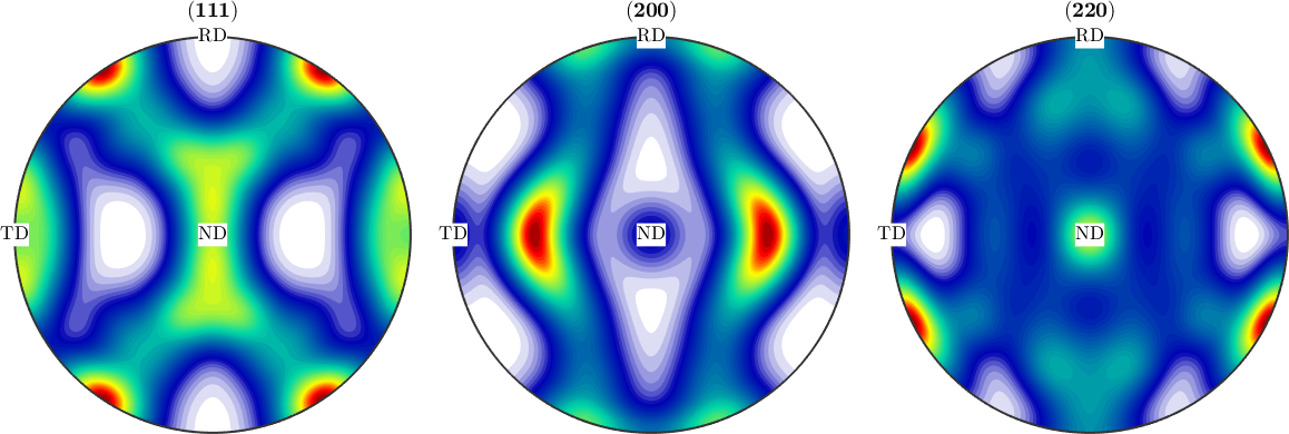
Each pole figure is symmetric about its horizontal and vertical axes. This is the pole-figure signature of the modelled orthotropic symmetry.
Simulate a Mounting Error
The known rotation below simulates a specimen mounted askew. Draw 1000 orientations from the model, apply the mounting rotation, and reconstruct an ODF by density estimation.
The sampled orientations inherit 222 specimen symmetry from the model. The stripSym method removes that group while keeping the rolling frame. The simulated observations then retain their physical RD, TD, and ND labels without claiming symmetry about the nominal plot axes.
% define the mounting rotation
rot = rotation.byEuler(15*degree,12*degree,-5*degree);

% sample without imposing symmetry, then rotate the observed texture
ori = discreteSample(odf,1000);
ori.SS = stripSym(ori.SS);
ori = rot * ori;

% estimate an ODF from the sampled orientations
odfEst = calcDensity(ori,'halfwidth',10*degree);

% plot the tilted estimate
plotPDF(odfEst,h,'antipodal',8,'silent')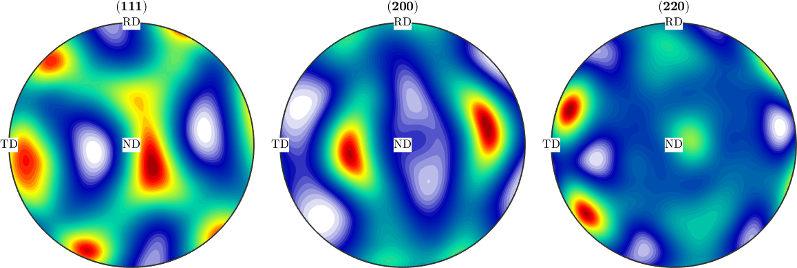
The lobes no longer pair across the displayed horizontal and vertical axes. They still form nearly symmetric pairs about tilted axes. Sampling and smoothing make those pairs approximate rather than exact.
Recover the Alignment
With no second argument, centerSpecimen starts its search near the \(x\) axis. The function reports a fit while locating each twofold axis. These values diagnose the optimization objective; they are not confidence levels or evidence that the orthotropic model is physically correct.
The returned rotation is the correction applied to the input ODF. Its inverse should therefore recover the known mounting rotation.
[odfCorrected,rotCorrection] = centerSpecimen(odfEst);

plotPDF(odfCorrected,h,'antipodal',8,'silent')

recoveryError = angle(rot,inv(rotCorrection)) / degree;
fprintf('difference between applied and recovered rotation: %.3f degree\n', ...
  recoveryError)
difference between applied and recovered rotation: 0.628 degree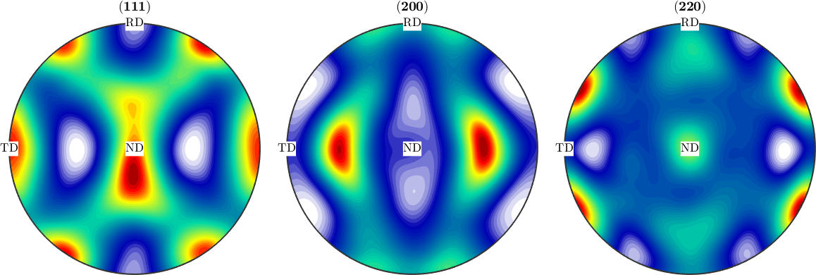
The horizontal and vertical mirror relationships have returned without imposing specimen symmetry on the reconstructed ODF. The printed difference is \(0.820^\circ\). It is not zero because the estimate uses a finite sample of 1000 orientations and a smoothing kernel.
Apply the Method to Measured Pole Figures
The same method applies to an ODF reconstructed from measured pole figures. Load the Aachen data and inspect the measurements before reconstruction.
fname = fullfile(mtexDataPath,'PoleFigure','aachen_exp.EXP');
pf = PoleFigure.load(fname);

plot(pf,'silent')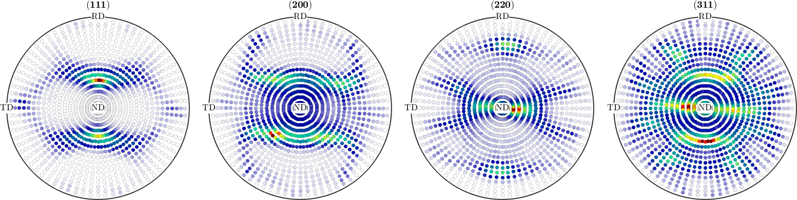
The measured pole figures already suggest horizontal and vertical symmetry, but their strongest features are slightly displaced from those axes. This visual impression motivates an alignment; it is not by itself proof of orthotropic symmetry.
Reconstruct and Locate the Symmetry Axes
Reconstruct the ODF as described in Reconstructing an ODF. The plot uses the same three pole families as the synthetic example.
odfMeasured = calcODF(pf,'silent');

plotPDF(odfMeasured,h,'antipodal','silent','noLabel','grid','on')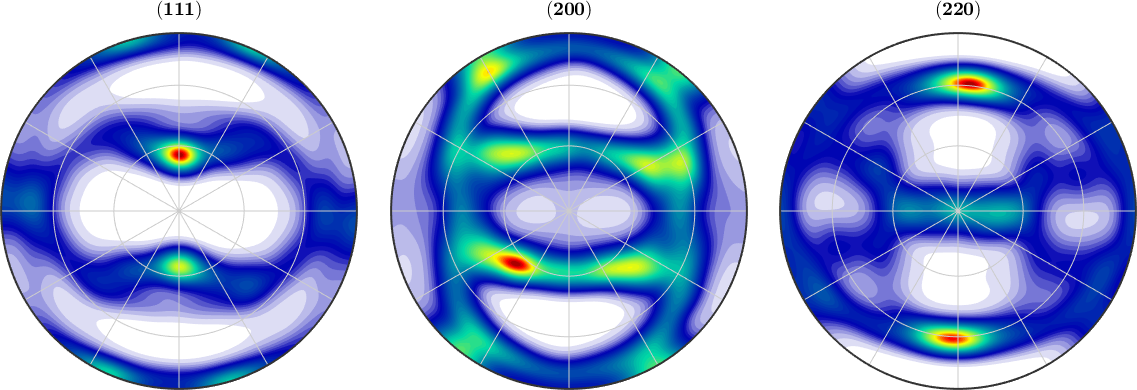
The density maxima nearly reflect across the nominal specimen axes, with a small common tilt. The common displacement is the pattern that centerSpecimen can quantify.
The second argument below starts the first-axis search near \(y\), the nominal TD. The 'Fourier' flag evaluates the symmetry mismatch from a harmonic representation. The third and fourth outputs are the twofold axes found in the uncorrected ODF.
[~,rotCorrection,a1,a2] = centerSpecimen(odfMeasured,vector3d.Y,'Fourier');

% orient the unoriented twofold axes towards the nominal RD, TD, and ND
rdAxis = -a2;
tdAxis = a1;
ndAxis = cross(rdAxis,tdAxis);

fprintf('mounting correction: %.3f degree\n',angle(rotCorrection)/degree)
fprintf('axis offsets from nominal RD, TD, ND: %.3f, %.3f, %.3f degree\n', ...
  angle(rdAxis,vector3d.X,'antipodal')/degree, ...
  angle(tdAxis,vector3d.Y,'antipodal')/degree, ...
  angle(ndAxis,vector3d.Z,'antipodal')/degree)

annotate([rdAxis,tdAxis,ndAxis],'label',{'RD','TD','ND'}, ...
  'backgroundcolor','w','MarkerSize',8)
mounting correction: 2.871 degree
axis offsets from nominal RD, TD, ND: 2.865, 2.871, 0.187 degree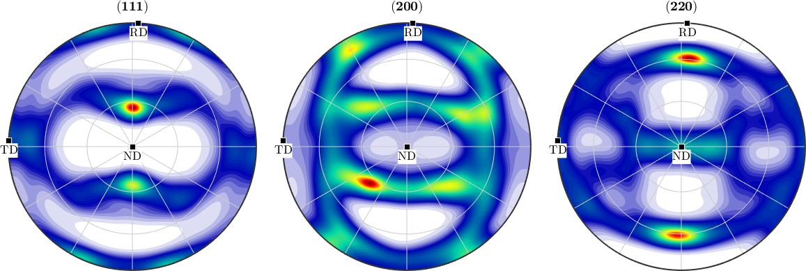
The annotations show the fitted RD, TD, and ND on the uncorrected pole figures. The fitted RD and TD share a small in-plane offset, while ND remains close to its nominal direction. The correction is \(2.871^\circ\). The RD, TD, and ND offsets are \(2.865^\circ\), \(2.871^\circ\), and \(0.187^\circ\). The signs of twofold axes are equivalent; they were chosen above only to place each label near its nominal positive direction.
Correct the alignment before assigning a nontrivial specimen symmetry. Imposing orthotropic symmetry first would average the texture over the wrong axes and could hide the mounting error.
Limits of Symmetry-Based Alignment
The method assumes that the ODF contains a strong enough orthotropic pattern to locate two perpendicular axes. Weak textures, genuine departures from orthotropic symmetry, multiple local optima, and a poor starting direction can make the fitted axes unreliable. The kernel halfwidth used for density estimation can also change the result. A smaller halfwidth does not necessarily improve the alignment.
Treat the correction as a model fit. Check several pole families, compare the axes with the specimen geometry, and repeat the search from another starting direction when the result is surprising. Do not use alignment to turn a genuinely asymmetric texture into an orthotropic one.
References
- H.-J. Bunge, Texture Analysis in Materials Science: Mathematical Methods, Butterworths, English ed., 1982, develops ODFs with crystal and specimen symmetry.
- A. C. Ott, I. Weissensteiner, A. R. Arnoldt, J. A. Oesterreicher and N. P. Papenberg, Automatic Texture Alignment by Optimization Method, Microscopy and Microanalysis 30 (2024), 253--277, compares automatic alignment with
centerSpecimenand examines texture spread, ODF halfwidth, and convergence to local minima. - ISO 3785:2023, Metallic materials -- Designation of test specimen axes in relation to product texture, specifies an orthogonal coordinate system for reporting test specimen axes relative to product texture.
Next
Specimen Symmetry explains what it means to impose the symmetry after alignment. Continue through the ODF chapter with ODF Shapes, which compares the kernels used to model and estimate orientation densities.
Citing this page.
This page is part of the documentation of
MTEX, a free and open
source MATLAB toolbox for analyzing and modeling crystallographic textures.
It was written by The MTEX Developers and is published at
https://mtex-toolbox.github.io/DetectionOfSampleSymmetry.html.
If you use MTEX, or reuse text or figures from this page, in your research,
please cite
F. Bachmann, R. Hielscher, H. Schaeben: Texture Analysis with MTEX - Free and Open Source Software Toolbox, Solid State Phenomena 160 (2010), 63-68. 10.4028/www.scientific.net/SSP.160.63
BibTeX
@article{bachmann2010mtex,
  author  = {F. Bachmann and R. Hielscher and H. Schaeben},
  title   = {Texture Analysis with MTEX - Free and Open Source Software Toolbox},
  journal = {Solid State Phenomena},
  volume  = {160},
  pages   = {63-68},
  year    = {2010},
  doi     = {10.4028/www.scientific.net/SSP.160.63},
  url     = {https://doi.org/10.4028/www.scientific.net/SSP.160.63}
}
Other papers describing specific MTEX methods are listed under Publications — please cite the one that best fits your application. The MTEX source code is licensed under the GNU General Public License v2.0; the text and figures of this documentation are licensed under CC BY 4.0, which permits reuse — including by automated systems — provided The MTEX Developers and this page are credited.