A grain is a phase-homogeneous, spatially connected region of EBSD pixels produced by segmentation. This page assumes that the grains have already been reconstructed as in Grain Reconstruction. Grain Boundary Properties introduces the boundary segments and their links to the neighbouring pixels.
EBSD data is measured on a regular grid, so a grain boundary comes out of calcGrains as a staircase of pixel edges. Every segment runs along one of the grid axes, whatever direction the boundary actually has. The staircase makes the boundary too long, quantizes its direction to a few values, and makes its curvature meaningless.
smoothBoundary repairs this geometry.
close all;
mtexdata csl silent
[grains,ebsd] = ebsd.calcGrains('minPixel',3);

grainsSmooth = smoothBoundary(grains,5);

ipfKey = ipfColorKey(grainsSmooth);
grainColor = ipfKey.orientation2color(grainsSmooth.meanOrientation);
plot(grainsSmooth,grainColor,'micronbar','off')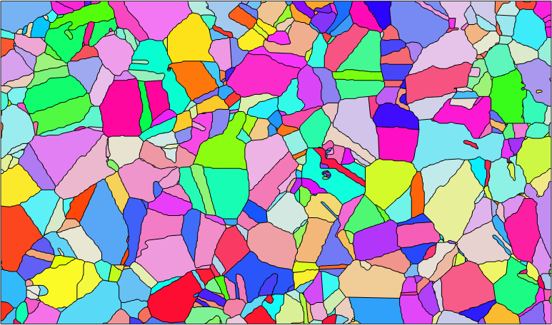
The colours distinguish the mean grain orientations. Smoothing changes the polygonal outlines, but it does not change the EBSD measurements, their orientations, or which measurements belong to each grain.
This page is about choosing and using the smoothing. How the stages work, and the full list of algorithms, is covered in Smoothing Algorithms.
What it does
Boundary smoothing has three stages, in this order. It removes the grid staircase, resamples the boundary at even spacing, and only then smooths the curve. The first two stages are not cosmetic. Smoothing a staircase directly only makes a finer staircase.
The measured boundary is grey below, and the result is magenta.
plot(grains.boundary,'lineWidth',4,'lineColor','LightGray',...
  'displayName','measured','micronbar','off')
hold on
plot(grainsSmooth.boundary,'lineWidth',2,'lineColor','Fuchsia',...
  'displayName','smoothed')
hold off
axis([313 353 140 156])
legend('Location','best')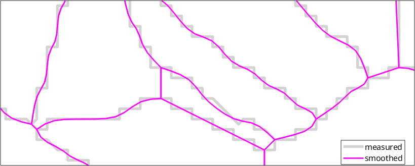
The magenta curves cut across the pixel steps while the junction locations remain fixed. A staircase along a boundary at 45 degrees is sqrt(2) times as long as the diagonal it represents. The whole map contains many boundary directions, so its measured change is data-dependent.
lenRaw = sum(grains.boundary('indexed').segLength);
lenSmooth = sum(grainsSmooth.boundary('indexed').segLength);

fprintf(['total boundary length: %.0f %s measured, %.0f %s smoothed' ...
  ' - %.0f%% shorter\n'],lenRaw,grains.scanUnit,lenSmooth,grains.scanUnit,...
  100*(1-lenSmooth/lenRaw))
total boundary length: 19419 um measured, 15648 um smoothed - 19% shorterThe direction distribution shows the same grid artifact. The raw boundary follows two antipodal grid axes, drawn as four spikes at multiples of 90 degrees. Smoothing spreads boundary length into the intervening directions, although some grid-aligned segments remain. Each panel has its own radial scale, so compare the angular spread rather than the bar heights.
figure
subplot(1,2,1)
histogram(grains.boundary('indexed').direction,...
  'weights',grains.boundary('indexed').segLength,180)
title('measured')
subplot(1,2,2)
histogram(grainsSmooth.boundary('indexed').direction,...
  'weights',grainsSmooth.boundary('indexed').segLength,180)
title('smoothed')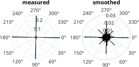
A measurement choice, not recovered truth
Smoothing suppresses a sampling artifact. It cannot recover the unmeasured sub-pixel path of the physical boundary. It replaces grid bias with a smaller, method-dependent geometric bias.
For quantitative comparisons, use the same reconstruction threshold, filter, and smoothing parameter for every map. Report those choices and repeat important measurements at nearby settings to check their sensitivity.
How much to smooth
The second argument is the number of smoothing iterations. More iterations give a smoother boundary and reduce the scatter around the grid directions. An iteration count is not a physical length, so the same count can have a different effect when the boundary sampling changes. See the warning about shrinkage below before increasing it.
iter = [1 5 10 25];
color = copper(length(iter)+1);

plot(grains.boundary,'lineWidth',1,'lineColor','LightGray',...
  'displayName','measured','micronbar','off')
for i = 1:length(iter)
  hold on
  plot(smoothBoundary(grains,iter(i)).boundary('i','i'),...
    'lineWidth',2,'lineColor',color(i,:),...
    'displayName',[num2str(iter(i)) ' iterations'])
end
hold off
axis([313 353 140 156])
legend('Location','best')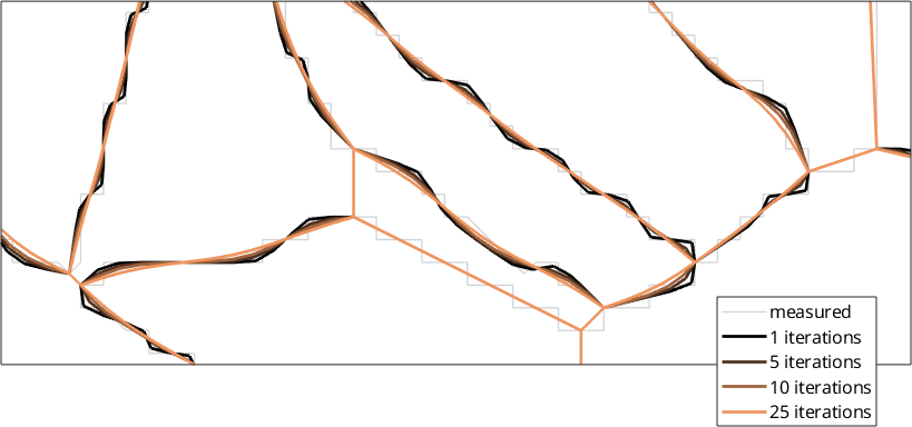
One iteration still tracks small pixel-scale bends. More iterations remove those bends, but the 25-iteration curve also pulls visibly inward around the small central grain. This is the shrinkage discussed next.
Which algorithm - the short version
A boundaryFilter selects the algorithm used for the final smoothing stage. Two choices cover most practical work.
Use the default when the smoothed boundary is for plotting or for measuring directions and lengths. It is a fast Laplacian, and it is what smoothBoundary(grains,5) selects without being asked.
Use taubinFilter when grain areas or shape parameters matter. A Laplacian shrinks. Every iteration pulls a convex region inward, and nothing bounds how far. Taubin follows every smoothing pass with a slightly larger unshrinking pass, which stops the systematic drift.
ref = smoothBoundary(grains,0); % simplified and resampled, not smoothed
A0 = ref.area;
d = median(grains.boundary.segLength);
big = A0 > 10*d^2;
A0 = A0(big);

grainsLaplace = smoothBoundary(grains,25);
aL = grainsLaplace.area;
aL = aL(big);
grainsTaubin = smoothBoundary(grains,taubinFilter(25));
aT = grainsTaubin.area;
aT = aT(big);

fprintf('grain area after 25 iterations\n')
fprintf(['  laplaceFilter (default) %+6.2f%% on average,' ...
  ' %+6.1f%% for the worst grain\n'],...
  100*mean((aL-A0)./A0),100*min((aL-A0)./A0))
fprintf(['  taubinFilter            %+6.2f%% on average,' ...
  ' %+6.1f%% for the worst grain\n'],...
  100*mean((aT-A0)./A0),100*min((aT-A0)./A0))
grain area after 25 iterations
laplaceFilter (default) -2.43% on average, -59.0% for the worst grain
taubinFilter -0.09% on average, -6.9% for the worst grainThe reference has passed through simplification and resampling but has zero smoothing iterations. The comparison excludes grains with an area no larger than 10*d^2, where d is the median raw segment length. The printed mean and worst cases show that Taubin removes the systematic area loss without promising exact area preservation.
The difference is visible on the grain whose area is closest to 30 square map units. The measured staircase is grey, the Laplacian is magenta, and Taubin is blue.
A = grains.area;
[~,id] = min(abs(A-30));
c = grains(id).centroid;

plot(grains(id).boundary,'lineWidth',4,'lineColor','LightGray',...
  'displayName','measured','micronbar','off')
hold on
plot(grainsLaplace(id).boundary,'lineWidth',2.5,...
  'lineColor','Fuchsia','displayName','Laplace, 25 iterations')
plot(grainsTaubin(id).boundary,...
  'lineWidth',2.5,'lineColor','DodgerBlue',...
  'displayName','Taubin, 25 iterations')
hold off
axis([c.x-6 c.x+6 c.y-6 c.y+6])
legend('Location','best')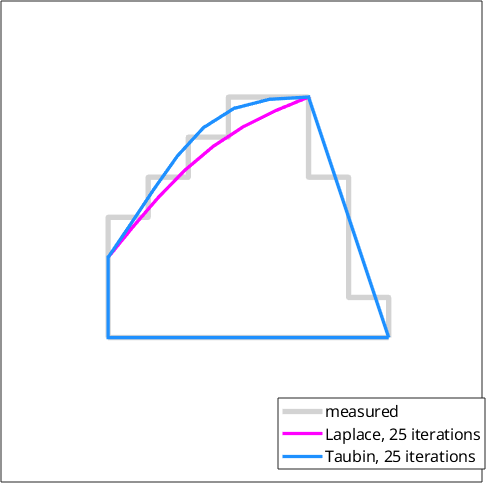
The magenta boundary cuts noticeably inside this small grain. The blue boundary stays much closer to the measured outline.
A physical smoothing length
curvatureFilter replaces the iteration count with a length: the wavelength whose amplitude is reduced by half. Finer detail is attenuated more strongly, while coarser detail is preserved more strongly. Because the parameter is a length, it has the same meaning for scans made at different step sizes.
F = curvatureFilter;
F.smoothingLength = 4; % in the units of the map, here um

plot(grains.boundary,'lineWidth',4,'lineColor','LightGray',...
  'displayName','measured','micronbar','off')
hold on
plot(smoothBoundary(grains,F).boundary,'lineWidth',2.5,...
  'lineColor','Orange','displayName','curvatureFilter, 4 um')
hold off
axis([313 353 140 156])
legend('Location','best')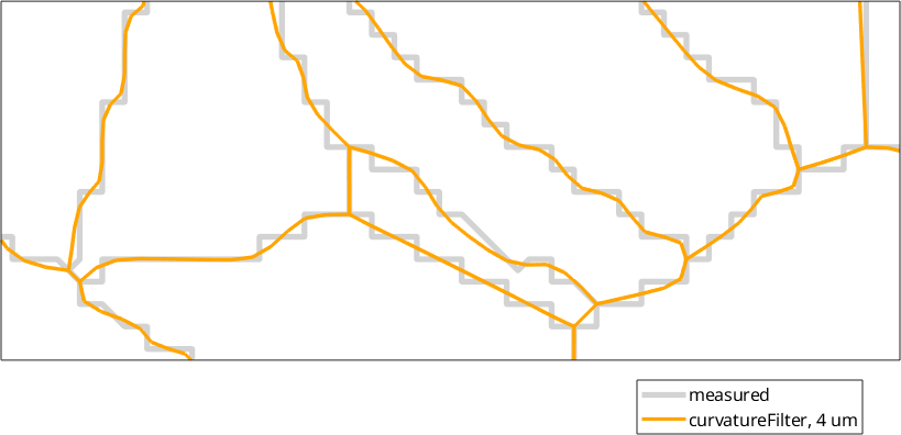
The orange curve removes pixel-scale turns but follows the larger bends of the measured boundary. Use one physical smoothing length across scans when their spatial resolutions differ.
huberFilter is available for faceted materials. It keeps genuine corners sharp instead of rounding them off. It is not a good default; see Smoothing Algorithms.
When to switch the first two stages off
Simplification and resampling change the number of boundary segments. A resampled segment no longer runs between one specific pair of pixels. Wherever gB.ebsdId is read per segment, for example to look up the orientations on either side, switch both stages off.
grainsPlain = smoothBoundary(grains,5,'noSimplify','noRefine');

fprintf(['boundary segments: %d measured, %d after smoothing, ' ...
  '%d with both steps off\n'],length(grains.boundary),...
  length(grainsSmooth.boundary),length(grainsPlain.boundary))
boundary segments: 21269 measured, 18452 after smoothing, 21269 with both steps offOnly the last count remains equal to the measured count. It therefore keeps one valid ebsdId pair for every original pixel-edge segment.
Junctions and triple points
A junction is a boundary vertex at which the number of meeting segments is not two. It includes triple and quadruple points as well as a loose end. By default, smoothBoundary holds every junction fixed. Segment connectivity is unchanged, and the places where the grains meet remain fixed.
The option 'moveTriplePoints' releases the interior junctions despite its narrower name. Be careful with a Laplacian: moving those vertices allows a small grain to shrink until its polygon collapses. Outer-boundary vertices remain fixed unless 'moveOuterBoundary' is also passed.
References
- D. H. Douglas and T. K. Peucker, "Algorithms for the Reduction of the Number of Points Required to Represent a Digitized Line or Its Caricature", The Canadian Cartographer 10 (1973), 112-122, doi:10.3138/FM57-6770-U75U-7727.
- G. Taubin, "A Signal Processing Approach to Fair Surface Design", Proceedings of SIGGRAPH 1995, 351-358, doi:10.1145/218380.218473.
- P. J. Huber, "Robust Estimation of a Location Parameter", The Annals of Mathematical Statistics 35 (1964), 73-101, doi:10.1214/aoms/1177703732.
- S. Fan et al., "Using Grain Boundary Irregularity to Quantify Dynamic Recrystallization in Ice", Acta Materialia 209 (2021), 116810, doi:10.1016/j.actamat.2021.116810.
- For standardized EBSD grain-size definitions and scope, see ISO 13067:2020 and ASTM E2627-13(2019).
Next
Continue with Smoothing Algorithms for the three-stage implementation, filter parameters, and quantitative comparisons. Then see Boundary Curvature for a measurement that depends directly on the smoothed geometry. The grain-level consequences for area, perimeter, and outline descriptors continue in Shape Parameters.
Citing this page.
This page is part of the documentation of
MTEX, a free and open
source MATLAB toolbox for analyzing and modeling crystallographic textures.
It was written by The MTEX Developers and is published at
https://mtex-toolbox.github.io/GrainSmoothing.html.
If you use MTEX, or reuse text or figures from this page, in your research,
please cite
F. Bachmann, R. Hielscher, H. Schaeben: Texture Analysis with MTEX - Free and Open Source Software Toolbox, Solid State Phenomena 160 (2010), 63-68. 10.4028/www.scientific.net/SSP.160.63
BibTeX
@article{bachmann2010mtex,
  author  = {F. Bachmann and R. Hielscher and H. Schaeben},
  title   = {Texture Analysis with MTEX - Free and Open Source Software Toolbox},
  journal = {Solid State Phenomena},
  volume  = {160},
  pages   = {63-68},
  year    = {2010},
  doi     = {10.4028/www.scientific.net/SSP.160.63},
  url     = {https://doi.org/10.4028/www.scientific.net/SSP.160.63}
}
Other papers describing specific MTEX methods are listed under Publications — please cite the one that best fits your application. The MTEX source code is licensed under the GNU General Public License v2.0; the text and figures of this documentation are licensed under CC BY 4.0, which permits reuse — including by automated systems — provided The MTEX Developers and this page are credited.