A crystal shape is a polyhedron bounded by lattice planes. In MTEX it is both a model of crystal habit and a three-dimensional glyph for an orientation. Rotating the glyph makes the orientation visible without reducing it to three angles.
This page assumes the distinction between lattice planes and directions from Miller Indices. The use of an orientation as a map from the crystal frame into the specimen frame is introduced in Orientations.
plottingConvention.default('y↑→x');A Simple Crystal Shape
Cubic and hexagonal crystals are often represented by a cube and a hexagonal prism. Their faces belong to the \(\{100\}\) family for the cube, and to the \(\{10\bar{1}0\}\) and \(\{0001\}\) families for the prism.
% load a hexagonal EBSD data set without displaying its map summary
mtexdata titanium silent

% construct a hexagonal prism in the crystal frame
cS = crystalShape.hex(ebsd.CS)
cS = crystalShape
mineral: Titanium (Alpha) (622, X||a, Y||b*, Z||c)
vertices: 12
faces: 8close all
plot(cS,'FaceAlpha',0.2)
drawNow(gcm,'final')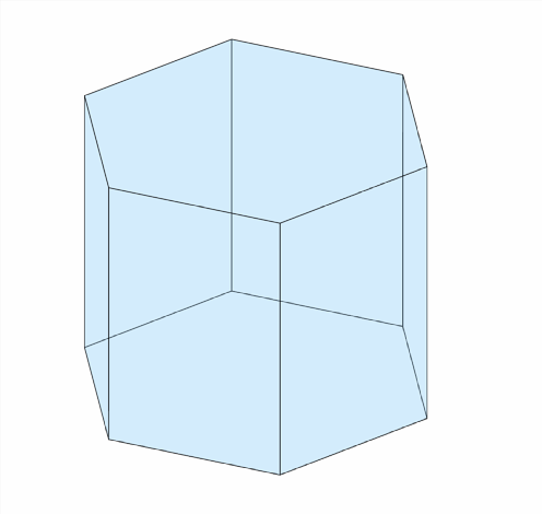
The display reports 12 vertices and 8 faces. The translucent drawing shows the six prism faces between the two basal faces.
A crystalShape stores the vertices in cS.V, face-to-vertex indices in cS.F, and edges in cS.E. The vertex coordinates printed below are expressed in the crystal frame.
cS.Vans = vector3d (y↑→x)
size: 12 × 1
x y z
-0.394 0 -0.308
-0.394 0 0.308
-0.197 -0.341 -0.308
-0.197 -0.341 0.308
-0.197 0.341 -0.308
-0.197 0.341 0.308
0.197 -0.341 -0.308
0.197 -0.341 0.308
0.197 0.341 -0.308
0.197 0.341 0.308
0.394 0 -0.308
0.394 0 0.308Planes and Slip Systems Inside the Shape
A slip system combines a lattice plane with a lattice direction in that plane. plotInnerFace and plotInnerDirection draw these parts separately. Passing a slip system directly to plot draws both.
sS = [slipSystem.pyramidal2CA(ebsd.CS), ...
  slipSystem.pyramidalA(ebsd.CS)]
sS = slipSystem (Titanium (Alpha))
size: 1 × 2
U V T W | H K I L CRSS
2 -1 -1 3 -2 1 1 2 1
2 -1 -1 0 0 1 -1 1 1plot(cS,'FaceAlpha',0.2)
hold on
plot(cS,sS(2),'FaceColor','blue')
plot(cS,sS(1),'FaceColor','red')
hold off
drawNow(gcm,'final')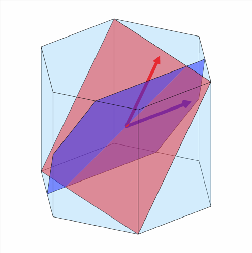
The blue and red patches are two different pyramidal planes. Their arrows make the distinct slip directions visible inside those planes. Their role in deformation is developed in Slip Systems.
Rotating, Scaling, and Shifting a Shape
The vertices of cS are in the crystal frame. Multiplication by an orientation expresses them in the specimen frame, just as it does for a crystal direction. Scaling changes the glyph size, while addition places the glyph at a specimen position.
% compute colours explicitly to avoid an unrelated colour-key message
ebsdKey = ipfColorKey(ebsd);
ebsdColor = ebsdKey.orientation2color(ebsd.orientations);

% plot the EBSD map in the specimen frame
close all
plot(ebsd,ebsdColor)

% select the orientation nearest the requested map position
ori = ebsd('xy',500,500).orientations;

% rotate, scale, and place one shape above that position
hold on
plot(500,500,50,ori * cS * 100,'FaceAlpha',0.5,'LineWidth',2)
hold off
drawNow(gcm,'final')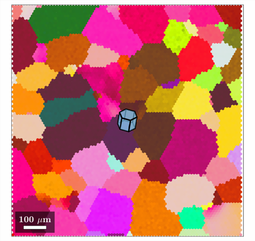
The crystal at the centre of the map is the same prism as before. Only its size, position, and expression in the specimen frame have changed.
The three operations also accept lists:
-
factor * cSscales a shape. -
ori * cSrotates it into a specimen orientation. -
[xy] + cSor[xyz] + cSshifts it to a specimen position.
This vectorization makes it possible to construct one glyph per grain. Grain reconstruction itself is taught in Grain Reconstruction.
% reconstruct grains and smooth only their boundary geometry
grains = calcGrains(ebsd);
grains = smoothBoundary(grains,5);

% colour grains by the specimen direction of the crystal c-axis
cKey = ipfColorKey(grains);
color = cKey.orientation2color(grains.meanOrientation);
plot(grains,color,'FaceAlpha',0.5,'LineWidth',2)

% retain grains with more than 50 measurements
isBig = grains.numPixel > 50;

% rotate and scale one shape for each retained grain
cSGrains = grains(isBig).meanOrientation * cS ...
  * 0.7 * sqrt(grains(isBig).area);

% place the shapes at the grain centroids
hold on
plot(grains(isBig).centroid + cSGrains, ...
  'FaceColor',color(isBig,:),'FaceAlpha',0.7)
hold off
drawNow(gcm,'final')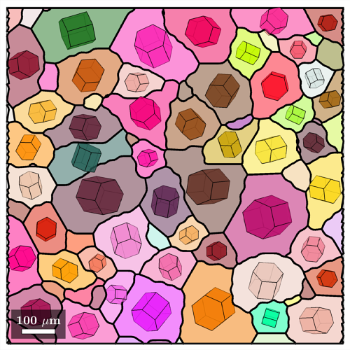
Similar colours mean that the crystal c-axes point in similar specimen directions. The shapes additionally show rotation about the c-axis, which a single inverse-pole-figure colour cannot encode. The colour construction is explained in IPF Maps.
These are idealized orientation glyphs. They do not measure the three-dimensional habit of a grain, and their projected outlines are not the measured two-dimensional grain boundaries.
Plotting Grain Glyphs Directly
The plot overload performs the rotation, scaling, and positioning from the previous section. It scales each glyph by the square root of grain area and places it at the grain centroid.
% plot the grain map
plot(grains,color,'FaceAlpha',0.5,'LineWidth',2)

% overlay one oriented crystal shape on each retained grain
hold on
plot(grains(isBig),0.7*cS,'FaceColor',color(isBig,:), ...
  'LineWidth',2,'FaceAlpha',0.7)
hold off
drawNow(gcm,'final')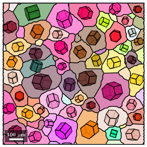
The result matches the explicit construction above. The direct call is shorter, while the explicit arithmetic remains useful when position or scale must follow another quantity.
A Twin Relationship
A twin law is a specific orientation relationship, not just a visually plausible rotation. Here two pairs of hexagonal lattice planes define an ideal extension-twin relationship. See Twinning for identifying that relationship in measured data.
twinning = orientation.map( ...
  Miller(0,1,-1,-2,ebsd.CS),Miller(0,-1,1,-2,ebsd.CS), ...
  Miller(2,-1,-1,0,ebsd.CS),Miller(2,-1,-1,0,ebsd.CS));

% draw the parent and twin shapes together
close all
plot(cS,'FaceAlpha',0.5)
hold on
plot(twinning * cS * 0.9,'FaceColor','orange')
hold off
view(45,20)
drawNow(gcm,'final')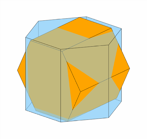
The parent and orange twin have the same faces and proportions. Their different placement makes the discrete orientation relationship visible.
Constructing a Shape from Face Normals
A cube or prism is often enough for an orientation glyph, but it is a poor model for many crystal habits. A more detailed shape starts from the normals of the faces that may bound it. Quartz provides a compact example.
cs = loadCIF('quartz');

% define representative face normals of quartz
m = Miller({1,0,-1,0},cs);   % hexagonal prism
r = Miller({1,0,-1,1},cs);   % positive rhombohedron
z = Miller({0,1,-1,1},cs);   % negative rhombohedron
s1 = Miller({2,-1,-1,1},cs); % left trigonal bipyramid
s2 = Miller({1,1,-2,1},cs);  % right trigonal bipyramid
x1 = Miller({6,-1,-5,1},cs); % left positive trapezohedron
x2 = Miller({5,1,-6,1},cs);  % right positive trapezohedron
MTEX expands each supplied normal by crystal symmetry. For a normal \(\mathbf{n}\), it retains points \(\mathbf{x}\) in the half-space \(\mathbf{x}\cdot\mathbf{n}\leq 1\) and intersects all such half-spaces. The length of the normal therefore encodes inverse face distance: a longer normal moves its plane towards the origin. Only relative distances matter, because MTEX normalizes the finished polyhedron.
% start from the prism and two rhombohedral forms
N = [m,r,z];
cS = crystalShape(N);

% report the geometry that actually bounds the polyhedron
nVertices = length(cS.V)
nActiveFaces = sum(isfinite(cS.faceArea) & cS.faceArea > 0)

plot(cS)
nVertices =
8
nActiveFaces =
12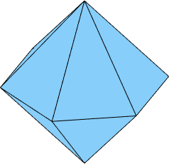
The polyhedron has eight vertices and twelve active rhombohedral faces. The six candidate prism faces do not appear because their planes lie beyond the intersections of the two rhombohedral forms.
% move the prism planes inwards
N = [2*m,r,z];
cS = crystalShape(N);
plot(cS,'colored')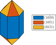
The prism now truncates the rhombohedra. Colour distinguishes the three face families and makes the new vertical faces easy to identify.
% move the negative rhombohedron inwards relative to the positive one
N = [2*m,r,0.9*z];
cS = crystalShape(N);
plot(cS,'colored')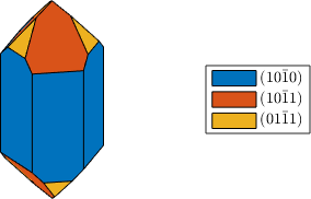
The two rhombohedral forms now have unequal face areas. Their angles are unchanged because the crystal symmetry and lattice metric are unchanged.
% add a bipyramid and a trapezohedron
N = [2*m,r,0.9*z,0.7*s1,0.3*x1];
cS = crystalShape(N);
plot(cS,'colored')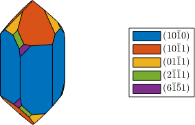
The small slanted faces break the apparent sixfold outline. The resulting form displays the trigonal symmetry of quartz rather than the symmetry of an ideal hexagonal prism.
Habitus and Extension Parameters
Individual face distances give direct control, but adjusting many of them is tedious. The constructor also implements the two-parameter heuristic of J. Enderlein, A package for displaying crystal morphology, Mathematica Journal 7(1), 1997. These parameters organize the distances; they are not measured growth rates or surface energies.
% take the face normals without individual scaling
N = [m,r,z,s2,x2];

habitus = 1;
extension = [1 1 1];
cS = crystalShape(N,habitus,extension);
plot(cS,'colored')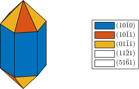
With unit parameters, the constructor derives all relative face distances from the indices alone.
extension controls the relative extent along the three lattice axes. Raising its second and third entries moves the corresponding limiting faces outwards.
extension = [1 1.2 1.1];
cS = crystalShape(N,habitus,extension);
plot(cS,'colored')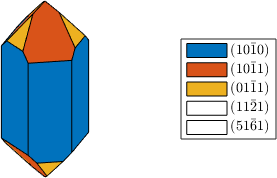
The changed axial proportions are visible in both the prism and the end faces. The legend still lists five input families, but at this habitus only the prism and the two rhombohedra bound the shape.
habitus controls how close faces with mixed indices come to the origin. The following sequence changes only that parameter.
habitus = 1.1;
cS = crystalShape(N,habitus,extension);
plot(cS,'colored'), snapnow

habitus = 1.2;
cS = crystalShape(N,habitus,extension);
plot(cS,'colored'), snapnow

habitus = 1.3;
cS = crystalShape(N,habitus,extension);
plot(cS,'colored')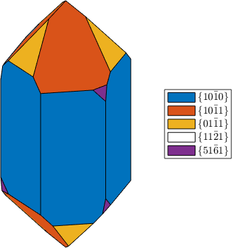
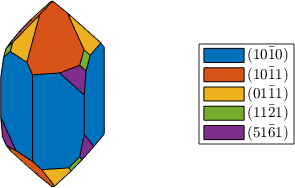
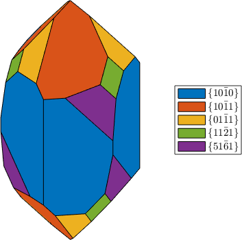
As habitus increases, the trapezohedral and bipyramidal faces grow at the expense of the prism. This sequence is a parameter study, not a simulated growth history.
Selecting a Face
Indexing a shape with a face normal selects the face with that outward normal. This is useful for highlighting one face or inspecting its faceArea. Supply a symmetrised list of normals to select a whole form.
plot(cS)
hold on
plot(cS(Miller(0,-1,1,0,cs)),'FaceColor','DarkRed')
hold off
camzoom(0.7)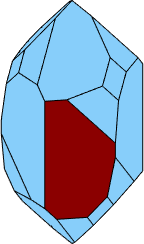
The dark-red patch isolates one prism face while the rest of the habit remains available for context.
Predefined Shapes
MTEX includes tuned shapes for common minerals. For example, crystalShape.olivine supplies the face families and their relative distances in one call.
plot(crystalShape.olivine,'colored')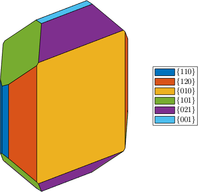
The large paired faces make the olivine model tabular. Other predefined models include crystalShape.garnet, crystalShape.topaz, and crystalShape.plagioclase.
Physical Meaning and Limits
A crystalShape constructs geometry from face normals and relative distances supplied by the user. It does not infer a habit from symmetry or crystal structure. Real habit also depends on growth conditions, so one mineral can develop different shapes.
If the supplied distances are proportional to orientation-dependent surface free energy, the same half-space intersection is the equilibrium Wulff construction. A growth shape instead requires relative face-growth rates. The distinction and the terminology of habit are summarized by the International Tables for Crystallography.
For broader physical background, see I. Sunagawa, Crystals: Growth, Morphology, and Perfection, Chapter 2, and P. Hartman and W. G. Perdok, On the relations between structure and morphology of crystals I.
Next
Advanced Crystal Shapes shows how to transfer face distances from the Smorf drawing tool. Return to Miller Indices for the planes represented by the faces, or continue to Fundamental Sector to see how crystal symmetry reduces direction space.
Citing this page.
This page is part of the documentation of
MTEX, a free and open
source MATLAB toolbox for analyzing and modeling crystallographic textures.
It was written by The MTEX Developers and is published at
https://mtex-toolbox.github.io/CrystalShapes.html.
If you use MTEX, or reuse text or figures from this page, in your research,
please cite
F. Bachmann, R. Hielscher, H. Schaeben: Texture Analysis with MTEX - Free and Open Source Software Toolbox, Solid State Phenomena 160 (2010), 63-68. 10.4028/www.scientific.net/SSP.160.63
BibTeX
@article{bachmann2010mtex,
  author  = {F. Bachmann and R. Hielscher and H. Schaeben},
  title   = {Texture Analysis with MTEX - Free and Open Source Software Toolbox},
  journal = {Solid State Phenomena},
  volume  = {160},
  pages   = {63-68},
  year    = {2010},
  doi     = {10.4028/www.scientific.net/SSP.160.63},
  url     = {https://doi.org/10.4028/www.scientific.net/SSP.160.63}
}
Other papers describing specific MTEX methods are listed under Publications — please cite the one that best fits your application. The MTEX source code is licensed under the GNU General Public License v2.0; the text and figures of this documentation are licensed under CC BY 4.0, which permits reuse — including by automated systems — provided The MTEX Developers and this page are credited.