
A tensile specimen cut from a rolled sheet can contract differently in its width and thickness directions. The Lankford parameter, also called the Lankford coefficient, R-value, or plastic strain ratio, measures this difference after plastic flow has begun:
\[R(\theta) = \frac{\epsilon_{\mathrm{width}}^{\mathrm p}} {\epsilon_{\mathrm{thickness}}^{\mathrm p}}.\]
Here \(\theta\) is the angle between the tensile direction and the rolling direction. Both transverse strains are usually negative, so their ratio is positive. An isotropic incompressible material has \(R=1\), not \(R=0\). A value near zero means that contraction occurs mainly through the sheet thickness, while a large value means that the sheet resists thinning.
Engineering sheets commonly have R-values from about 1 to 2.5 or higher. Values close to zero, or even slightly negative, can also be reported. These ranges are not universal material classes, and a low R-value should not be interpreted as more isotropic deformation. calcLankford searches the ordinary tensile-contraction range \(0\leq\rho\leq1\), corresponding to nonnegative model R-values.
Why the R-value matters
A high average R-value generally improves resistance to thinning during cup drawing, hole expansion, and other sheet-forming operations. This is useful for complex automotive and aerospace parts such as body panels. Variation of \(R(\theta)\) within the sheet plane is a different effect. It promotes nonuniform flow and can produce ears around a drawn cup.
It is sometimes claimed that a low R-value is preferable when uniform deformation is needed, for example when deep drawing cylindrical containers or cans. That claim confuses normal and planar anisotropy. A high average R-value resists thinning, while small directional variation is what helps a cylindrical cup draw without pronounced ears or uneven thickness that would require trimming.
Experimentally, tensile specimens are cut at several angles to the rolling direction. Width and thickness strains are measured at a specified length strain in the uniform plastic regime. Using transverse strain divided by axial strain would not give the Lankford parameter.
MTEX estimates \(R(\theta)\) from crystallographic orientations and a deformation-system model. The calculation uses the equal-strain Taylor theory introduced in Taylor Model. It predicts a texture contribution to plastic anisotropy rather than replacing a tensile test or accounting for every source of formability.
One ideal Brass orientation
Start with the ideal fcc Brass component \((110)[1\bar{1}2]\) and the fcc slip family. The critical resolved shear stress (CRSS) is one for every system, so only crystallographic geometry distinguishes them.
CS = crystalSymmetry('m-3m',[1 1 1],'mineral','fcc');
sS = slipSystem.fcc(CS)
ori = orientation.brass(CS);
sS = slipSystem (fcc)
u v w | h k l CRSS
0 1 -1 1 1 1 1The Taylor strain path is parameterized by \(\rho=-\epsilon_{\mathrm{width}}^{\mathrm p}/ \epsilon_{\mathrm{length}}^{\mathrm p}\). Plastic incompressibility gives \(R=\rho/(1-\rho)\). The finite grid below therefore tests eleven possible transverse contractions rather than solving for a continuous R-value. Values outside \(0\leq\rho\leq1\) would make one transverse direction extend during the tensile increment and are not accepted by this model.
rho = linspace(0,1,11);
[R,M,minM] = calcLankford(ori,sS,'silent','rho',rho);
By default, calcLankford evaluates tensile directions from 0 to 90 degrees in 5 degree steps. Rows of M correspond to rho and columns to tensile directions. Plot three columns to compare rolling-direction, diagonal, and transverse-direction tension with Fig. 3.10 of Hosford.
plot(rho,M(:,[1 10 19]).','-s','lineWidth',2);
xlabel('{\rho} = -{\epsilon}_w^p / {\epsilon}_l^p');
ylabel('Taylor factor, M');
legend('\theta=0^\circ','\theta=45^\circ','\theta=90^\circ', ...
  'Location','northeast');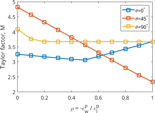
The three curves have different minima, so changing the in-plane tensile direction changes the preferred contraction path. At 45 and 90 degrees, the minimum lies at \(\rho=1\) and MTEX reports \(R=\mathrm{Inf}\). This is a boundary result of the sampled strain paths: the model selects zero thickness strain, rather than failing to return a prediction.
Broaden the ideal texture
A real sheet does not contain one exact orientation. Model a 10 degree spread around the Brass component with a unimodal orientation distribution function (ODF), which describes the orientation density of the texture.
odf = unimodalODF(ori,'halfwidth',10*degree)
[ROdf,MOdf,minMOdf] = calcLankford(odf,sS,'silent','rho',rho);

plot(rho,MOdf(:,[1 10 19]).','-s','lineWidth',2);
xlabel('{\rho} = -{\epsilon}_w^p / {\epsilon}_l^p');
ylabel('Texture-averaged Taylor factor, M');
legend('\theta=0^\circ','\theta=45^\circ','\theta=90^\circ', ...
  'Location','northeast');
odf = SO3FunRBF (fcc → y↓→x)
unimodal component
kernel: de la Vallee Poussin, halfwidth 10°
center: 1 orientations
Bunge Euler angles in degree
phi1 Phi phi2 weight
35 45 0 1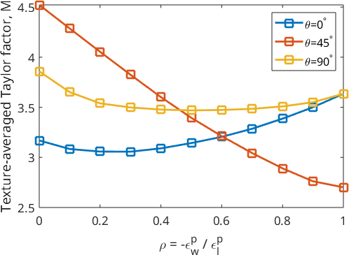
The ODF averages the response of nearby orientations. Compare these curves with the sharp-component curves above: their positions and depths change because the minimum now represents the whole texture, not only the ideal Brass orientation.
Estimate the R-value from an EBSD map
The final example uses an hcp titanium EBSD map. An EBSD orientation map supplies a texture estimate resolved in space, but this calculation uses one mean orientation and one area weight per reconstructed grain.
mtexdata titanium
CS = ebsd.CS;
[grains,ebsd] = calcGrains(ebsd,'angle',5*degree,'minPixel',6);

plot(ebsd,ebsd.orientations)
hold on
plot(grains.boundary,'lineWidth',2)
hold off
ebsd = EBSDhex (y↓→x)
Phase Orientations Mineral Color Symmetry Crystal reference frame
0 8100 (99%) Titanium (Alpha) LightSkyBlue 622 X||a, Y||b*, Z||c
Properties: ci, grainid, iq, sem_signal, oldId
Scan unit : um
X × Y × Z : [0 → 996] × [0 → 998] × [0 → 0]
Normal vector: (0,0,1)
Hex grid :97 × 84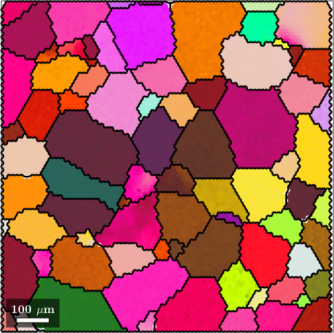
Colour changes show the measured orientation variation, while the black lines show the grains whose mean orientations enter the calculation. Intragranular orientation spread is therefore not represented below.
Choose the hcp deformation systems
Taylor theory needs enough independent deformation systems to reproduce an imposed strain. Combine basal, prismatic, and pyramidal slip with compressive twinning. The second argument of each constructor is its relative CRSS, so the values 1, 66, 80, and 100 strongly affect the prediction.
TODO: MTEX currently symmetrises every deformation system with both shear senses. Consequently, twinC1 acts here as a reversible pseudo-slip family. A polarity-aware implementation is still needed for one-way twinning and detwinning.
sS = [slipSystem.basal(CS,1), ...
  slipSystem.prismatic2A(CS,66), ...
  slipSystem.pyramidalCA(CS,80), ...
  slipSystem.twinC1(CS,100)]
sS = slipSystem (Titanium (Alpha))
size: 1 × 4
U V T W | H K I L CRSS
1 1 -2 0 0 0 0 1 1
0 1 -1 0 2 -1 -1 0 66
2 -1 -1 3 -1 1 0 1 80
-1 1 0 -2 -1 1 0 1 100Compute the directional response
Evaluate tensile directions every 5 degrees from the notional rolling direction, which is the specimen x-axis by default. The specimen z-axis is the sheet normal. Pixel counts provide area weights on this regular map, so larger grains contribute proportionally more to the texture.
theta = linspace(0,90*degree,19);
[R,M,minM] = calcLankford(grains.meanOrientation,sS,theta, ...
  'weights',grains.numPixel,'silent');

plot(theta./degree,R,'o-r','lineWidth',1.5)
xlabel('Angle from rolling direction, \theta (degrees)')
ylabel('Lankford parameter, R')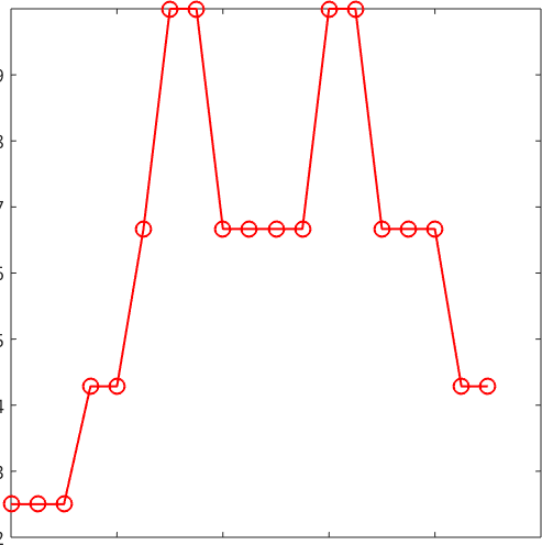
\(R\) changes in abrupt steps because of the finite \(\rho\) grid that calcLankford searches. A finer grid resolves the preferred contraction path more closely but costs additional Taylor solves.
The change between levels is planar anisotropy: specimens cut at different in-plane angles are predicted to contract by different width to thickness ratios. Here \(R_0=0.25\), \(R_{45}=0.66667\), and \(R_{90}=0.42857\). Read these values together with the assumed CRSS values.
plot(theta./degree,minM,'o-b','lineWidth',1.5)
xlabel('Angle from rolling direction, \theta (degrees)')
ylabel('Minimum normalized plastic work, min(M)')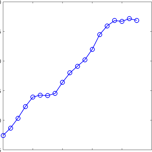
M is the CRSS-weighted slip activity per unit imposed strain. It is the normalized plastic work used to select the contraction path. When every CRSS is one, as in the Brass example, it equals the geometric Taylor factor. Its angular variation need not follow \(R(\theta)\) because the path and the work needed to achieve it are different outputs.
Average and planar anisotropy
Three standard values summarize the 0, 45, and 90 degree predictions. The normal anisotropy ratio, also written \(\bar R\), Ravg, or \(r_m\), measures resistance to thickness contraction. Values at or above one indicate resistance to thinning; values below one indicate that thinning is the preferred transverse flow direction and raise the risk of failure in drawing operations.
A normalization pitfall is to multiply the weighted sum by one half. The following expression gives 1.0060 for this map, which is twice the standard average and must not be used as \(\bar R\).
twiceRbar = 0.5 * (R(1) + R(19) + 2*R(10))twiceRbar =
1.0060Divide the weighted sum by four. For this map, the correctly normalized value is \(\bar R=0.50298\).
Rbar = 0.25 * (R(1) + R(19) + 2*R(10))Rbar =
0.5030The planar anisotropy parameter \(\Delta R\) measures the difference between the 0/90 degree response and the 45 degree response. A value of zero is commonly used as an indicator of the fourfold earing tendency in an orthotropic rolled sheet. A value near zero suppresses that contribution, but it neither requires equal R-values at every angle nor guarantees an ear-free cup.
deltaR = 0.5 * (R(1) + R(19) - 2*R(10))deltaR =
-0.3274Here \(\Delta R=-0.32738\). Its sign says that the predicted 45 degree R-value is larger than the average of the 0 and 90 degree values.
% Close generated figures before the reference section.
close all
References
- W. T. Lankford, S. C. Snyder, and J. A. Bauscher, New criteria for predicting the press performance of deep drawing sheets, Transactions of the American Society for Metals 42 (1950), 1197--1231, introduces the plastic strain ratio as a criterion for sheet drawability.
- W. F. Hosford, The Mechanics of Crystals and Textured Polycrystals, Oxford University Press, 1993, develops the Taylor-model construction and gives the ideal-Brass curves reproduced in the first example.
Citing this page.
This page is part of the documentation of
MTEX, a free and open
source MATLAB toolbox for analyzing and modeling crystallographic textures.
It was written by The MTEX Developers and is published at
https://mtex-toolbox.github.io/Lankford.html.
If you use MTEX, or reuse text or figures from this page, in your research,
please cite
F. Bachmann, R. Hielscher, H. Schaeben: Texture Analysis with MTEX - Free and Open Source Software Toolbox, Solid State Phenomena 160 (2010), 63-68. 10.4028/www.scientific.net/SSP.160.63
BibTeX
@article{bachmann2010mtex,
  author  = {F. Bachmann and R. Hielscher and H. Schaeben},
  title   = {Texture Analysis with MTEX - Free and Open Source Software Toolbox},
  journal = {Solid State Phenomena},
  volume  = {160},
  pages   = {63-68},
  year    = {2010},
  doi     = {10.4028/www.scientific.net/SSP.160.63},
  url     = {https://doi.org/10.4028/www.scientific.net/SSP.160.63}
}
Other papers describing specific MTEX methods are listed under Publications — please cite the one that best fits your application. The MTEX source code is licensed under the GNU General Public License v2.0; the text and figures of this documentation are licensed under CC BY 4.0, which permits reuse — including by automated systems — provided The MTEX Developers and this page are credited.