
A grain is a phase-homogeneous, spatially connected part of an EBSD map. It contains many measured orientations rather than one exact orientation. When those orientations follow one dominant rotation, they trace a fibre in orientation space. The axis of that fibre is the grain's dispersion axis.
This page develops the construction for one grain and then repeats it over a map. Read Grain Reconstruction and Selecting Grains first if grains and grain ids are new to you. Orientation Parameters introduces the grain mean, GROD, and grain orientation spread.
A dispersion axis is an axis, not a directed vector. Its two ends are equivalent. Its crystal-frame representation can constrain a deformation mechanism, while its specimen-frame representation can constrain the kinematics. Neither interpretation follows from the fit alone.
plottingConvention.default('y↑→x');
mtexdata forsterite silent
[grains,ebsd] = calcGrains(ebsd,'minPixel',5);
Find a grain with coherent intragranular rotation
First colour each forsterite measurement by its misorientation from the mean orientation of its own grain. The hue gives the misorientation axis in the specimen frame, and the saturation gives the angle. The reference orientation is supplied per measurement through ck.oriRef.
ck = axisAngleColorKey(ebsd('f').CS);
ck.oriRef = grains('id',ebsd('f').grainId).meanOrientation;
plot(ebsd('f'),ck.orientation2color(ebsd('f').orientations))

hold on
plot(grains.boundary,'lineWidth',2)
plot(grains({'En','Di'}),'FaceAlpha',0.7)
hold off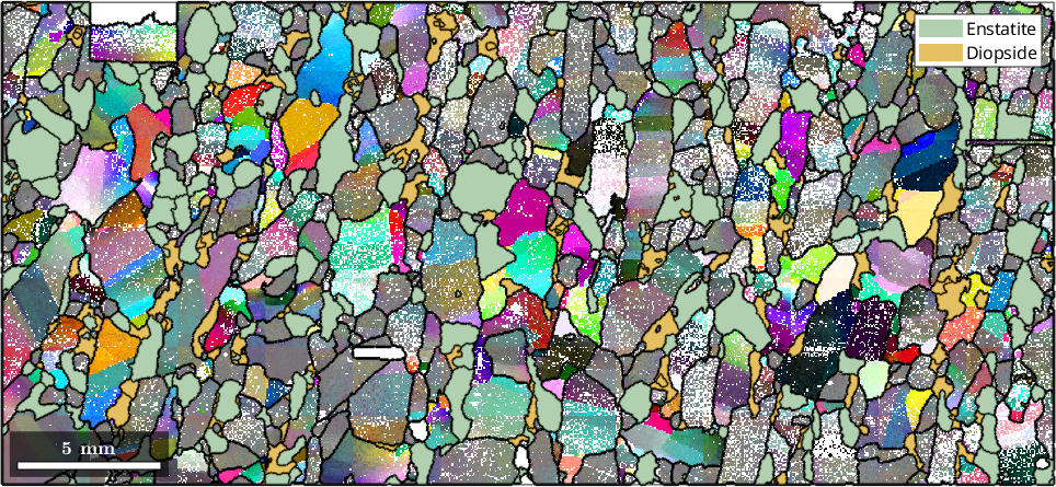
Pale grains have little rotation relative to their means. A grain with one strong hue has rotated mainly about one specimen axis. Bands of two or three hues instead warn that more than one axis may be active.
The white outline selects one large, strongly coloured grain. The rest of the single-grain analysis asks whether its apparent axis survives a quantitative fit.
grainSelected = grains(5095,7803);
hold on
plot(grainSelected.boundary,'lineWidth',3,'lineColor','w')
hold off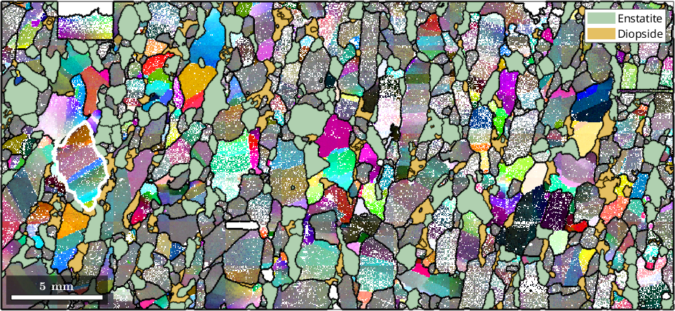
See the dispersion in a pole figure
Start with a grid of crystal directions. Every orientation in the selected grain maps every grid direction into the specimen frame. Each grid direction becomes a small cloud, and how far that cloud spreads measures how much the intragranular rotation moves the direction.
s2G = equispacedS2Grid('resolution',15*degree);
s2G = Miller(s2G,ebsd('f').CS);
ori = ebsd(grainSelected).orientations;
directions = ori .* s2G;

plot(directions,'MarkerSize',3,'upper')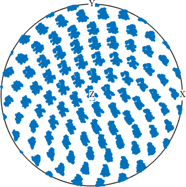
At this scale the clouds all look alike. What separates them is how far each one spreads, so colour every cloud by its mean angular deviation.
poleDispersion = mean(angle(mean(directions),directions),'omitmissing');

plot(directions,repmat(poleDispersion,length(ori),1)./degree,...
  'MarkerSize',3)
mtexColorbar('title','average pole dispersion in degree')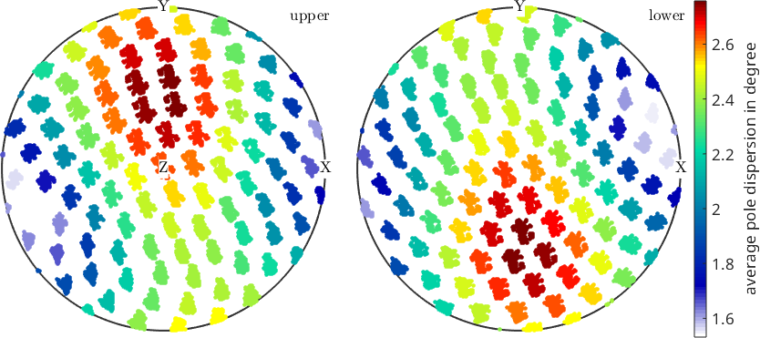
The darkest blue cloud moves least. A rotation leaves its own axis fixed, so that crystal direction gives a grid-based estimate of the dispersion axis in the specimen frame.
[~,idMin] = min(poleDispersion);
axisGrid = grainSelected.meanOrientation .* s2G(idMin);
annotate(axisGrid)
annotate(axisGrid,'plane','lineStyle','--','lineWidth',2)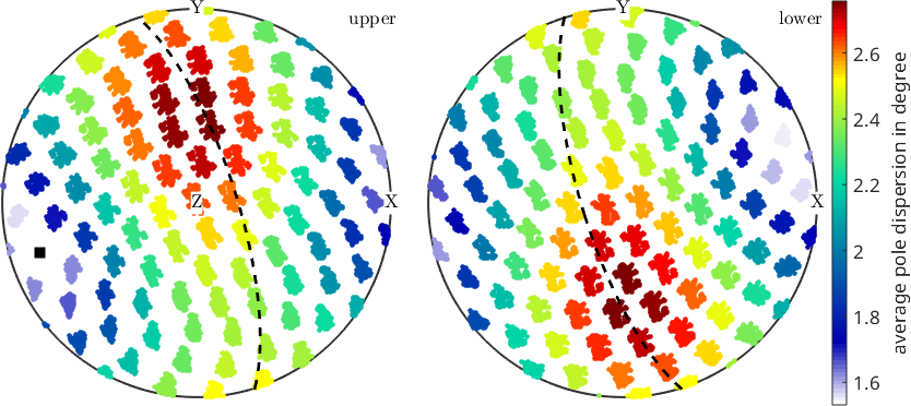
The dashed great circle is normal to the black axis. The streaks follow that circle, as rotation about the axis requires. This construction is deliberately coarse: it can return only one of the 15 degree grid nodes. The spacing is a sampling resolution, not a 15 degree uncertainty bound.
Fit a fibre without a direction grid
Orientations produced by one continuous rotation lie on an orientation fibre. fibre.fit fits that curve directly. The 'local' algorithm is intended for a concentrated orientation cloud such as the orientations inside one grain.
fib = fibre.fit(ori,'local')fib = fibre (Forsterite → y↑→x)
h || r: (1̅1̅1̅2) || (-12,-5,3)The fitted fibre reports the same physical axis in two reference frames. fib.h is the crystal direction and fib.r is the specimen direction. Reference Frame Alignment explains why the specimen interpretation depends on a correctly calibrated frame.
fib.h
fib.r

annotate(fib.r,'MarkerFaceColor','r')
annotate(fib.r,'plane','lineStyle','-.','lineWidth',2,'lineColor','r')

gridFitDifference = angle(axisGrid,fib.r,'antipodal')./degree;
fprintf('Grid axis to fitted axis: %.1f degree\n',gridFitDifference)
ans = Miller (Forsterite)
h k l
-1.0363 -9.5489 1.6628
ans = vector3d (y↑→x)
x y z
-0.899 -0.377 0.225
Grid axis to fitted axis: 6.3 degree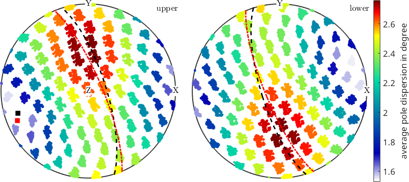
The printed separation is smaller than the grid spacing. The black and red estimates therefore agree at the resolution of the grid, while the fitted result is not restricted to a grid node.
Decide whether the grain really has one axis
A best fit always exists, even for a round cloud with no meaningful axis. The two additional outputs from fibre.fit diagnose that case. lambda contains the four eigenvalues of the quaternion orientation tensor in ascending order. fitAngle is the mean angular distance from the fitted fibre.
[fib,lambda,fitAngle] = fibre.fit(ori,'local');

lambda
fitAngle./degree
lambda =
0.0000 0.0002 0.0006 0.9991
ans =
1.5419The largest eigenvalue, \(\lambda_4\), records overall concentration. The next, \(\lambda_3\), records extension along the fibre, while \(\lambda_2\) records scatter away from it. Their ratio is a useful screening statistic for this example.
fibreRatio = lambda(3)./lambda(2)fibreRatio =
3.5912Here the printed ratio is well above one, so the cloud is more line-like than round. The cutoff of three used below is a heuristic for this page, not a universal MTEX threshold. A defensible cutoff also depends on EBSD angular precision, grain size, cleaning, and the deformation expected.
Small-angle rotation axes are especially sensitive to EBSD error. Do not interpret a stable-looking axis from a nearly uniform grain without first checking the angle scale and the fit.
Locate departures from the fitted fibre
The distance from each orientation to the fibre shows where the one-axis model works and where it fails. The left panel shows the line in orientation space. The right panel returns the same residual to the map.
distanceFromFibre = angle(fib,ori)./degree;
plot(ori,distanceFromFibre,'all')
xlim([0 30]); ylim([20 70]); zlim([80 120])
grid minor
hold on
plot(fib,'lineWidth',2)
hold off

nextAxis
plot(ebsd(grainSelected),distanceFromFibre)
mtexColorbar('title','distance from fibre in degree')

fprintf(['Distance from fibre: median %.2f degree, 90th percentile ' ...
  '%.2f degree, maximum %.2f degree\n'],...
  median(distanceFromFibre,'omitmissing'),...
  quantile(distanceFromFibre,0.9),...
  max(distanceFromFibre,[],'omitmissing'))
Distance from fibre: median 1.41 degree, 90th percentile 2.51 degree, maximum 4.45 degree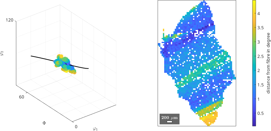
Most points lie close to the fitted line. A band across the middle and the tail at the bottom lie farther away. Those coherent residuals are where a single dispersion axis is least adequate; they may record a second rotation or a subgrain boundary.
Fit all sufficiently sampled grains
A fit is made separately for every forsterite grain with more than 100 measurements. Small grains are excluded because their orientation clouds do not sample a fibre well enough for this comparison.
grainsLarge = grains('fo');
grainsLarge = grainsLarge(grainsLarge.numPixel > 100);

axisCrystal = Miller.nan(length(grainsLarge),1,grainsLarge.CS);
axisSpecimen = vector3d.nan(length(grainsLarge),1);
fibreRatio = nan(length(grainsLarge),1);

for k = 1:length(grainsLarge)

  [fib,lambda] = fibre.fit(ebsd(grainsLarge(k)).orientations,'local');

  axisCrystal(k) = fib.h;
  axisSpecimen(k) = fib.r;
  fibreRatio(k) = lambda(3)./lambda(2);

end

isFibre = fibreRatio > 3;
fprintf(['Large forsterite grains: %d; ratio above three: %d ' ...
  '(%.1f percent)\n'],length(grainsLarge),nnz(isFibre),...
  100*nnz(isFibre)./length(grainsLarge))
Large forsterite grains: 249; ratio above three: 141 (56.6 percent)Only the grains that pass the stated screen enter the aggregate plots. The others are not proved to have no physical rotation axis; this orientation data simply do not support reporting one by this criterion.
Compare axes in the specimen frame
The dots show individual antipodal axes. The contours show a kernel density estimate with a 15 degree halfwidth. Its units are multiples of a uniform distribution, so one is the uniform reference.
specimenDensity = calcDensity(axisSpecimen(isFibre),...
  'halfwidth',15*degree,'antipodal');
[maxSpecimenDensity,peakSpecimenAxis] = max(specimenDensity);

plot(axisSpecimen(isFibre),'contourf','antipodal','upper',...
  'halfwidth',15*degree)
hold on
plot(axisSpecimen(isFibre),'antipodal','upper','MarkerSize',4)
hold off
mtexColorbar

fprintf('Maximum specimen-axis density: %.2f multiples of uniform\n',...
  maxSpecimenDensity)
peakSpecimenAxis
Maximum specimen-axis density: 1.96 multiples of uniform
peakSpecimenAxis = vector3d (y↑→x)
antipodal: true
x y z
0.961 0.0626 0.271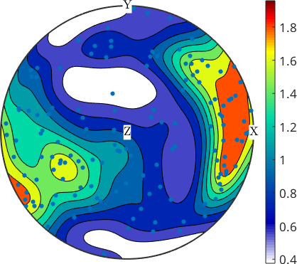
The preference is mild rather than uniform. The axes avoid the centre of the projection, which is the section normal, and gather near the rim towards X. They therefore tend to lie in the section and point roughly east--west. Such a specimen-frame cluster can indicate a common kinematic rotation axis, but calling it a vorticity axis requires the geological and deformation context.
Compare axes in the crystal frame
The crystal-frame plot asks a different question. A preferred crystal direction can constrain a common rotation mechanism across differently oriented grains.
crystalDensity = calcDensity(axisCrystal(isFibre),...
  'halfwidth',15*degree);
[maxCrystalDensity,peakCrystalAxis] = max(crystalDensity);

plot(axisCrystal(isFibre),'contourf','antipodal','fundamentalRegion',...
  'halfwidth',15*degree)
mtexColorbar

fprintf('Maximum crystal-axis density: %.2f multiples of uniform\n',...
  maxCrystalDensity)
peakCrystalAxis = Miller(peakCrystalAxis,grainsLarge.CS)
Maximum crystal-axis density: 2.92 multiples of uniform
peakCrystalAxis = Miller (Forsterite)
antipodal: true
h k l
0 10.207 0.0004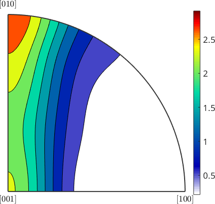
This maximum is stronger and lies near [010], with density falling towards [100]. The forsterite grains therefore bend about their own [010] direction more often than about other crystal directions in this map. A rotation axis can narrow the candidate slip mechanisms, but it does not identify a unique slip system without boundary geometry or dislocation evidence.
Keep the two frames separate. A specimen-frame cluster supports a shared kinematic frame, while a crystal-frame cluster supports a shared crystallographic mechanism. This data set shows both preferences, with the crystal-frame preference the stronger of the two.
References
- Z. D. Michels, B. Tikoff, S. C. Kruckenberg and J. R. Davis, "Determining vorticity axes from grain-scale dispersion of crystallographic orientations", Geology 43 (2015), 803--806, doi:10.1130/G36868.1. This paper develops crystallographic vorticity-axis analysis from grain-scale dispersion axes.
- S. M. Reddy and C. Buchan, "Constraining kinematic rotation axes in high-strain zones: a potential microstructural method", Geological Society, London, Special Publications 243 (2005), 1--10, doi:10.1144/GSL.SP.2005.243.01.02.
- D. J. Prior, "Problems in determining the misorientation axes, for small angular misorientations, using electron backscatter diffraction in the SEM", Journal of Microscopy 195 (1999), 217--225, doi:10.1046/j.1365-2818.1999.00572.x. This is the measurement-precision caution behind the small-angle warning above.
Next
Grain Reference Orientation Deviation develops the angle and axis of every measurement relative to its grain reference. Axis Distribution Function treats axes of grain-boundary misorientations and explains their symmetry and random references. The next page in this chapter, Grain Neighbours, changes from intragranular orientation structure to the network formed by adjacent grains.
Citing this page.
This page is part of the documentation of
MTEX, a free and open
source MATLAB toolbox for analyzing and modeling crystallographic textures.
It was written by The MTEX Developers and is published at
https://mtex-toolbox.github.io/Grain_dispersion_axes.html.
If you use MTEX, or reuse text or figures from this page, in your research,
please cite
F. Bachmann, R. Hielscher, H. Schaeben: Texture Analysis with MTEX - Free and Open Source Software Toolbox, Solid State Phenomena 160 (2010), 63-68. 10.4028/www.scientific.net/SSP.160.63
BibTeX
@article{bachmann2010mtex,
  author  = {F. Bachmann and R. Hielscher and H. Schaeben},
  title   = {Texture Analysis with MTEX - Free and Open Source Software Toolbox},
  journal = {Solid State Phenomena},
  volume  = {160},
  pages   = {63-68},
  year    = {2010},
  doi     = {10.4028/www.scientific.net/SSP.160.63},
  url     = {https://doi.org/10.4028/www.scientific.net/SSP.160.63}
}
Other papers describing specific MTEX methods are listed under Publications — please cite the one that best fits your application. The MTEX source code is licensed under the GNU General Public License v2.0; the text and figures of this documentation are licensed under CC BY 4.0, which permits reuse — including by automated systems — provided The MTEX Developers and this page are credited.