
This tutorial starts with reconstructed grains and asks what lies between them. It selects one phase pair, maps the misorientation angle, and finds the dominant angle population in a magnesium specimen.
Read the grain tutorial first if grain reconstruction or inverse pole figure colours are new to you. General Concepts explains how one MTEX object holds a vectorized list of grains or boundary segments.
A grain boundary is a segment between two neighbouring EBSD pixels that belong to different grains. MTEX stores the complete boundary network as a grainBoundary object with one entry per segment.
close all;
plottingConvention.default('y↑→x');

% load the magnesium example without displaying the full EBSD summary
mtexdata twins silent

% reconstruct grains using an explicit example threshold
grains = calcGrains(ebsd,'angle',15*degree);

% smooth the pixel staircases before measuring boundary trace lengths
grains = grains.smoothBoundary;

% display the grain summary
grains
grains = grain2d (y↑→x)
Phase Grains Pixels Mineral Symmetry Color
1 121 22833 Magnesium 6/mmm LightSkyBlue
boundary segments: 3359 (954 µm)
inner boundary segments: 3 (0.95 µm)
triple points: 114
Properties: meanRotation, GOSSee the grains before measuring their boundaries
The displayed summary reports 121 magnesium grains. The 15 degree reconstruction threshold is an example parameter, not a universal grain definition. Grain Reconstruction explains how to choose and report it.
smoothBoundary simplifies, refines, and smooths the pixel staircase by default. This improves trace geometry but changes the number and length of segments. Grain Smoothing develops that choice.
% create one explicit inverse pole figure colour key
ipfKey = ipfColorKey(grains.CS);
grainColor = ipfKey.orientation2color(grains.meanOrientation);

% plot one mean orientation colour per grain
plot(grains,grainColor)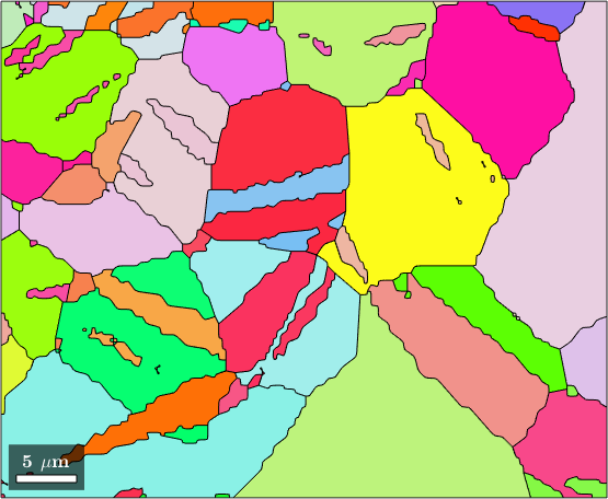
Reading the orientation map
The narrow lamellae crossing the larger grains have colours that differ abruptly from their surroundings. Their shape and orientation contrast make them candidates for twins, but the boundary relationship must still be measured.
The boundary list
The boundary network is a list in its own right. Displaying it groups the segments by the phases on their two sides.
gB = grains.boundarygB = grainBoundary (y↑→x)
Segments length mineral 1 mineral 2
608 182 µm notIndexed Magnesium
2751 772 µm Magnesium MagnesiumReading the boundary summary
The summary reports 3359 segments after smoothing. Of these, 2751 lie between two magnesium grains and 608 form the outer rim, which appears in the notIndexed row because there is no grain on its other side.
In a general map the same row can also contain boundaries next to notIndexed measurements. notIndexed is the phase for measurements whose diffraction patterns could not be indexed.
The outer-rim segments have no second indexed lattice and therefore no crystallographic misorientation. Two phase names select the segments that do have magnesium on both sides.
gB_MgMg = gB('Magnesium','Magnesium')gB_MgMg = grainBoundary (y↑→x)
Segments length mineral 1 mineral 2
2751 772 µm Magnesium MagnesiumMisorientation angle along the boundary
A misorientation is the rotation that carries one crystal lattice onto the other. Crystal symmetry gives many equivalent rotations for the same physical relationship. The angle property reports the smallest symmetry-equivalent rotation angle, also called the disorientation angle.
A boundary has no preferred side. MTEX therefore gives same-phase boundary misorientations grain-exchange symmetry, so a rotation and its inverse represent the same relationship. See Grain Exchange Symmetry.
% store one disorientation angle per magnesium boundary segment in degrees
misorientationAngle = gB_MgMg.misorientation.angle ./ degree;

% colour every selected segment by that angle
figure
plot(gB_MgMg,misorientationAngle,'linewidth',2)
mtexColorbar('title','minimum misorientation angle (degree)')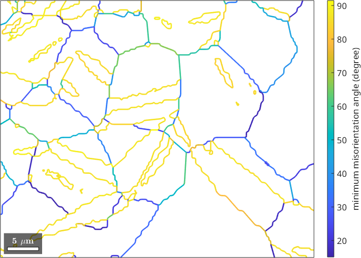
Reading the angle map
Long lamellar boundaries share nearly the same high-angle colour. Other interfaces cover a broader angular range, so the map already suggests one repeated orientation relationship.
Measure the dominant angle population
The next two displayed values summarize segments, not whole physical interfaces. The median angle is 84.7 degrees, and 58 percent of the segments have angles above 80 degrees.
medianAngle = median(misorientationAngle)
fractionAbove80 = mean(misorientationAngle > 80)
medianAngle =
84.6791
fractionAbove80 =
0.5816Reading the segment statistics
Segment counts depend on how a traced curve was sampled. For a boundary population it is usually more meaningful to weight every segment by its trace length. The histogram below sums trace length in 2 degree bins.
edges = 0:2:94;
[~,~,binId] = histcounts(misorientationAngle,edges);
traceLength = accumarray(binId,gB_MgMg.segLength,[numel(edges)-1 1]);

% display the angular range containing the most boundary trace length
[~,peakBin] = max(traceLength);
peakRange = edges(peakBin:peakBin+1)

% plot total boundary trace length in each angular bin
figure
histogram('BinEdges',edges,'BinCounts',traceLength)
xlabel('minimum misorientation angle (degree)')
ylabel('boundary trace length (micrometres)')
title('Magnesium to magnesium boundaries')
peakRange =
86 88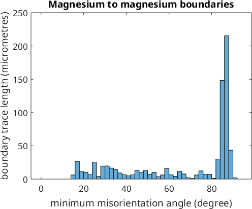
Reading the angle distribution
The dominant bin spans 86 to 88 degrees. Its position agrees with the 86.3 degree disorientation of the common magnesium extension-twin relationship, and the contributing traces are the lamellae seen above.
An angle match alone does not identify a twin. A robust test compares the complete misorientation, including its axis, with the ideal relationship and checks where the selected boundaries occur. Twinning performs that test and Merging Grains reconnects the twin with its host.
What a two-dimensional map leaves unknown
A macroscopic grain boundary has five degrees of freedom. Three describe the misorientation and two describe the boundary-plane normal. A polished two-dimensional section records only the line where that plane cuts the surface, called its trace; the plane inclination is not measured directly.
The angle map therefore describes the lattice relationship across each trace, not the complete boundary character. Three-dimensional mapping or a stereological estimate over many traces is needed for the missing plane information. Boundary Normal Distribution explains the planar-section approach.
Next
Continue with Grain Boundaries for the boundary chapter. Selecting Boundaries develops phase and property selections, while Boundary Properties explains the geometry and paired pixel information stored per segment.
Boundary Misorientations develops angles and axes. Misorientation Distribution Functions explains the reference distributions needed before a boundary population is compared with random orientations.
Further reading
- A.P. Sutton and R.W. Balluffi, Interfaces in Crystalline Materials, Oxford University Press, 1995.
- A.P. Sutton, E.P. Banks and A.R. Warwick, The five-dimensional parameter space of grain boundaries, Proceedings of the Royal Society A 471 (2015), 20150442.
- D.M. Saylor, B.S. El-Dasher, B.L. Adams and G.S. Rohrer, Measuring the five-parameter grain-boundary distribution from observations of planar sections, Metallurgical and Materials Transactions A 35 (2004), 1981-1989.
- J.W. Christian and S. Mahajan, Deformation twinning, Progress in Materials Science 39 (1995), 1-157.
Citing this page.
This page is part of the documentation of
MTEX, a free and open
source MATLAB toolbox for analyzing and modeling crystallographic textures.
It was written by The MTEX Developers and is published at
https://mtex-toolbox.github.io/BoundaryTutorial.html.
If you use MTEX, or reuse text or figures from this page, in your research,
please cite
F. Bachmann, R. Hielscher, H. Schaeben: Texture Analysis with MTEX - Free and Open Source Software Toolbox, Solid State Phenomena 160 (2010), 63-68. 10.4028/www.scientific.net/SSP.160.63
BibTeX
@article{bachmann2010mtex,
  author  = {F. Bachmann and R. Hielscher and H. Schaeben},
  title   = {Texture Analysis with MTEX - Free and Open Source Software Toolbox},
  journal = {Solid State Phenomena},
  volume  = {160},
  pages   = {63-68},
  year    = {2010},
  doi     = {10.4028/www.scientific.net/SSP.160.63},
  url     = {https://doi.org/10.4028/www.scientific.net/SSP.160.63}
}
Other papers describing specific MTEX methods are listed under Publications — please cite the one that best fits your application. The MTEX source code is licensed under the GNU General Public License v2.0; the text and figures of this documentation are licensed under CC BY 4.0, which permits reuse — including by automated systems — provided The MTEX Developers and this page are credited.