
An orientation answers one question: how is this crystal placed in this specimen? In MTEX it maps coordinates from the crystal frame into the specimen frame. It is the bridge between the sample sitting on the stage and the lattice inside it.
A reference frame is the coordinate system in which data are expressed. The crystal frame is fixed to the lattice, while the specimen frame is fixed to the sample. An orientation relates those frames and carries the symmetry attached to each one. It is therefore more than three Euler angles or a bare rotation matrix.
Everything in texture analysis builds on this idea. A texture is a population of orientations. A pole figure shows where selected crystal directions point. A misorientation is the relative map between two crystal frames. Get the definition right here and the rest of MTEX follows. Get it wrong and every later plot is rotated by something you cannot find.
A Crystal Placed in the Specimen
The most direct picture of an orientation is the crystal where it sits. This example uses one cubic crystal and one Bunge Euler-angle triplet.
cs = crystalSymmetry('m-3m');
cS = crystalShape.cube(cs);
ori = orientation.byEuler(30*degree,50*degree,10*degree,'Bunge',cs);

plot(ori * cS,'colored','faceAlpha',0.35);
hold on;
arrow3d(0.62*[vector3d.X,vector3d.Y,vector3d.Z],...
  'faceColor','black','label',{'X','Y','Z'});
hold off;
camzoom(0.8);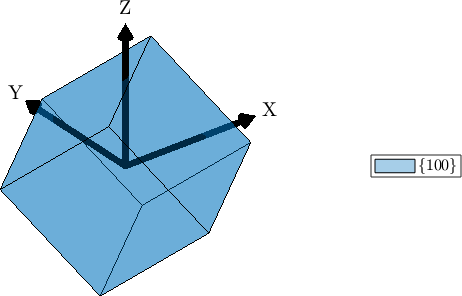
The blue cube and its \((100)\) face-family label remain fixed to the crystal. The black X, Y and Z arrows remain fixed to the specimen. The orientation is the relationship between them, not either frame by itself.
Three independent choices can change the numbers or the picture. An active rotation turns an object, while a passive rotation changes coordinates. The two maps are inverses. Second, several Euler-angle conventions use the same three symbols in different ways. Third, the Cartesian crystal frame can be aligned with the lattice axes in different ways. Most disagreements between two people's orientation results begin with one of these choices.
MTEX makes the map direction and Euler convention explicit. The Crystal Reference System explains the independent crystal-frame alignment. A plotting convention describes how a reference frame is laid out on screen; it is not the orientation or the symmetry.
Symmetry Makes an Orientation a Set
A crystal cannot distinguish settings related by its point-group symmetry. One physical orientation therefore has many equivalent descriptions. A cubic crystal has 24 proper symmetry rotations, and all 24 describe the same physical placement.
The full point group m-3m also contains 24 improper operations, so MTEX can list 48 symmetry-related orthogonal transformations. Only the 24 proper operations can reorient a rigid crystal. The distinction matters when a calculation separates rotations from reflections or inversion.
Symmetry is also why "the angle between two orientations" needs care. MTEX compares their proper-symmetry descriptions and returns the smallest rotation angle. Comparing only the stored representatives makes the result depend on how the same physical orientations happened to be labelled.
A fundamental region is the part of rotation space used to retain one representative from each equivalence class. Representatives on its boundary can be tied, so MTEX also needs a consistent boundary convention. The corresponding construction for crystal directions is the fundamental sector.
Prerequisites
Start with Defining Three-Dimensional Vectors. Then read the plane and direction notation in Miller Indices and the Euler-angle representations in Defining Rotations. Crystal Symmetries supplies the point-group background. The plotting pages also use Spherical Projections.
Recommended Reading Order
The chapter contents give the recommended core route. Definition constructs orientations from Euler angles, matrices, crystal directions, and random samples. Theory then develops the crystal-to-specimen map. Symmetry explains the equivalent descriptions. Standard Orientations introduces named components such as Goss, Brass, and Cube. MTEX vs. Bunge Convention completes this foundation. Read it before trusting Euler angles you did not produce yourself.
The next four pages compare ways to look at orientations. Pole Figures fix a crystal direction and ask where it points in the specimen. Inverse Pole Figures ask which crystal direction lies along a specimen direction. Both are projections and discard information. 3D Plots retain all three rotational degrees of freedom. Section Plots cut that space into two-dimensional slices. They retain more information than projections but are harder to read.
Fundamental Regions explains the symmetry-dependent domains in those plots. Specimen Symmetry covers invariance of the sample texture. That differs from symmetry of the crystal lattice. Rolling and other processes may impose it.
The remaining pages treat sets and workflows. Grids constructs finite samples of orientation space. Fibres constructs the curves followed by many real textures. Import and Export handle files and their conventions.
Embeddings represents orientations as points in a linear space so that averaging and machine learning are well behaved. It is last in the chapter contents, but it assumes misorientation theory. Read that page before returning to Embeddings.
References
- H.-J. Bunge, Texture Analysis in Materials Science: Mathematical Methods, Butterworths, 1982. It establishes the orientation and Euler-angle conventions of texture analysis.
- A. Morawiec, Orientations and Rotations: Computations in Crystallographic Textures, Springer, 2004. It develops rotation space, symmetry, and orientation statistics.
- D. Rowenhorst et al., Consistent representations of and conversions between 3D rotations, Modelling and Simulation in Materials Science and Engineering 23, 083501, 2015. It compares rotation conventions and gives reproducible conversion rules.
- ISO 24173:2024, Microbeam analysis - Guidelines for orientation measurement using electron backscatter diffraction. It gives current guidance for reproducible EBSD orientation measurements.
Next
The relative orientation of two crystals is Misorientations. A whole population described as a density rather than a list is an ODF. Orientations measured on a grid across a sample are EBSD.
Citing this page.
This page is part of the documentation of
MTEX, a free and open
source MATLAB toolbox for analyzing and modeling crystallographic textures.
It was written by The MTEX Developers and is published at
https://mtex-toolbox.github.io/CrystalOrientations.html.
If you use MTEX, or reuse text or figures from this page, in your research,
please cite
F. Bachmann, R. Hielscher, H. Schaeben: Texture Analysis with MTEX - Free and Open Source Software Toolbox, Solid State Phenomena 160 (2010), 63-68. 10.4028/www.scientific.net/SSP.160.63
BibTeX
@article{bachmann2010mtex,
  author  = {F. Bachmann and R. Hielscher and H. Schaeben},
  title   = {Texture Analysis with MTEX - Free and Open Source Software Toolbox},
  journal = {Solid State Phenomena},
  volume  = {160},
  pages   = {63-68},
  year    = {2010},
  doi     = {10.4028/www.scientific.net/SSP.160.63},
  url     = {https://doi.org/10.4028/www.scientific.net/SSP.160.63}
}
Other papers describing specific MTEX methods are listed under Publications — please cite the one that best fits your application. The MTEX source code is licensed under the GNU General Public License v2.0; the text and figures of this documentation are licensed under CC BY 4.0, which permits reuse — including by automated systems — provided The MTEX Developers and this page are credited.