
Below the elastic limit, removing a load lets a crystal recover its shape. Beyond that limit, some deformation remains. Plastic deformation is carried mainly by crystal slip and, in suitable materials and loading states, by deformation twinning.
Crystal slip moves dislocations so that one part of the lattice shears past another on a particular plane and in a particular direction. A plane together with an in-plane shear direction is a slip system. Densely packed planes and directions are often easy slip paths because the atomic translation is short, but packing density alone does not define the active systems. Their resistance also depends on the material, temperature, strain rate, and microstructure.
This is why plasticity belongs in a texture toolbox. Slip systems are fixed in the crystal frame, so the response of a grain depends on its orientation relative to the load. Plastic deformation is anisotropic for the same geometric reason as elasticity. Slip also rotates the lattice, so deformation changes the texture and therefore changes the later response.
See one slip system
Use one representative of the fcc \(\{111\}\langle110\rangle\) family in aluminium. The red disk is the slip plane and the arrow in the disk is the Burgers vector, which supplies the shear direction.
plottingConvention.default('y↑→x');

cs = crystalSymmetry('m-3m','mineral','Aluminium');
cS = crystalShape.cube(cs);
sS = slipSystem.fcc(cs);

plot(cS,'faceAlpha',0.2)
hold on
plot(cS,sS,'faceColor','red')
hold off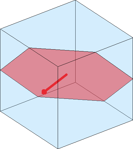
The arrow lies in the plane, so the direction is perpendicular to the plane normal. Crystal symmetry expands this representative into four planes with three directions in each. There are twelve geometric systems, or twenty-four entries if the two shear senses are stored separately.
sSGeometric = sS.symmetrise('antipodal');
sSSigned = sS.symmetrise;
[length(sSGeometric),length(sSSigned)]
ans =
12 24Which system slips?
A slip system responds only to the part of the applied stress that shears its plane along its Burgers vector. This component is the resolved shear stress. The dimensionless Schmid factor relates it to a uniaxial applied stress, depends only on geometry, and ranges in magnitude from zero to one half.
Schmid's law says that slip begins when the resolved shear stress reaches the critical resolved shear stress (CRSS). With equal CRSS values, the system with the largest suitably signed Schmid factor activates first. This is a useful first answer and a poor last one: an isolated-grain calculation ignores the neighbours that constrain the grain.
Polycrystal bounds
A polycrystal model must decide what all grains share. The Taylor model assumes that every grain undergoes the specimen strain. Reproducing a general deviatoric strain needs five independent shear systems and usually gives an upper bound on strength.
The Sachs model makes the opposite assumption. Every grain feels the same stress and slips independently on its best system, so compatibility is not enforced and the predicted strength is a lower bound. These assumptions parallel the uniform-strain and uniform-stress bounds used in elasticity. Real grains compromise between them.
The Sachs and single-slip models share an independent-grain premise, but they are not the same calculation. Sachs gives a strength bound under a common stress. The single-slip texture model follows the lattice rotation produced when one prescribed system carries the deformation.
Follow the chapter
Begin with Slip Systems to construct a plane, Burgers vector, symmetry-equivalent family, and CRSS values. Then use Schmid Factor to resolve a crystal or specimen stress and apply the calculation to an EBSD grain map. The parallel Deformation Twinning branch explains why a signed shear factor needs extra care for a polar twin system.
The polycrystal sequence starts with Taylor Model, the equal-strain limit. Sachs Model then develops the equal-stress lower bound. Single Slip Model follows the texture evolution of independently slipping crystals, and Slip Transmission tests whether selected systems can carry shear across a boundary between neighbouring grains.
Measure dislocation content
Dislocation Systems defines the Burgers vector, line direction, tensor basis, and energy weights of edge and screw dislocations. GND uses measured orientation gradients to fit densities of chosen geometrically necessary dislocation systems. WBV instead estimates a net weighted Burgers vector without choosing those systems first.
A gradient of orientation inside a grain requires a geometrically necessary dislocation content to preserve compatibility. This provides one of the few routes from an orientation map to a defect-density estimate, but the result is not a direct or unique measurement. Two-dimensional EBSD leaves tensor components unknown, and the inferred densities depend on the candidate systems, noise treatment, and energy assumptions.
Evolve and summarize a texture
VPSC imports texture and slip-activity histories from the visco-plastic self-consistent code. Texture Evolution computes an incremental Taylor history inside MTEX instead. Taylor Hex applies that model to magnesium, where the deformation families have unequal and temperature-dependent strengths.
Finally, Lankford uses the Taylor model to predict the plastic strain ratio of a rolled sheet as the tensile direction changes. That page distinguishes the average resistance to thinning from the in-plane variation that promotes earing.
Related foundations
Recovered deformation is introduced in Elasticity. Both elastic and plastic models use the objects developed in Tensors. The orientation gradients used for dislocation analysis come from EBSD, while candidate twin boundaries are identified in Twinning Analysis.
% Close the generated figure before the closing sections.
close all
References
- G. I. Taylor, Plastic Strain in Metals, Journal of the Institute of Metals 62 (1938), 307--324, introduces the equal-strain polycrystal model and its minimum-work construction.
- U. F. Kocks, C. N. Tomé and H.-R. Wenk, Texture and Anisotropy, Cambridge University Press, 1998, develops slip-system geometry, the Sachs and Taylor bounds, and deformation-induced texture evolution.
Next
Continue with Slip Systems to turn the red plane and arrow above into MTEX objects, generate the complete crystallographic family, and assign its critical resolved shear stress.
Citing this page.
This page is part of the documentation of
MTEX, a free and open
source MATLAB toolbox for analyzing and modeling crystallographic textures.
It was written by The MTEX Developers and is published at
https://mtex-toolbox.github.io/Plasticity.html.
If you use MTEX, or reuse text or figures from this page, in your research,
please cite
F. Bachmann, R. Hielscher, H. Schaeben: Texture Analysis with MTEX - Free and Open Source Software Toolbox, Solid State Phenomena 160 (2010), 63-68. 10.4028/www.scientific.net/SSP.160.63
BibTeX
@article{bachmann2010mtex,
  author  = {F. Bachmann and R. Hielscher and H. Schaeben},
  title   = {Texture Analysis with MTEX - Free and Open Source Software Toolbox},
  journal = {Solid State Phenomena},
  volume  = {160},
  pages   = {63-68},
  year    = {2010},
  doi     = {10.4028/www.scientific.net/SSP.160.63},
  url     = {https://doi.org/10.4028/www.scientific.net/SSP.160.63}
}
Other papers describing specific MTEX methods are listed under Publications — please cite the one that best fits your application. The MTEX source code is licensed under the GNU General Public License v2.0; the text and figures of this documentation are licensed under CC BY 4.0, which permits reuse — including by automated systems — provided The MTEX Developers and this page are credited.