
A reference frame is the coordinate system in which data are expressed. A crystal frame is the Cartesian reference frame fixed to the lattice basis of a phase. Its basis and default plotting convention are distinct from the point-group symmetry attached to it.
This page explains how the non-orthogonal lattice axes \(\vec a\), \(\vec b\) and \(\vec c\) are embedded in an orthonormal crystal frame \(\vec x\), \(\vec y\), \(\vec z\). Read Miller Indices and Lattice Metric and Plane Geometry first if direct and reciprocal lattice axes are new to you.
A crystalFrame stores the point symmetry and lattice metric of a phase and carries its crystal frame. The display below therefore reports both the metric and the frame alignment.
import numpy as np
from mtex import *
plottingConvention.default('y↑→x')
cs = crystalFrame('triclinic', [1, 2.2, 3.1], np.array([80, 85, 95]) * degree)
cs
crystalFrame (⊙c*→b)
  symmetry          : 1̅
  elements          : 2
  a, b, c           : 1, 2.2, 3.1
  alpha, beta, gamma: 80°, 85°, 95°
  reference frame   : X||a*, Z||c
Why an Orthonormal Frame Is Needed
The direct lattice axes are generally neither perpendicular nor of equal length. Orientations and tensor components, however, use orthonormal Cartesian components. The lattice basis must therefore be embedded in a Cartesian crystal frame, and that embedding is a convention.
An orientation maps the crystal frame to a specimen frame. A specimen frame describes the sample, such as a measurement or rolling frame; it is not the crystal frame discussed here. See EBSD Reference Frame for specimen-frame calibration.
A second convention decides which physical lattice vectors are called \(\vec a\), \(\vec b\) and \(\vec c\). That choice is treated in Crystal Axes Alignment.
Orthogonal Crystal Systems
In orthorhombic, tetragonal and cubic lattices, each direct axis is parallel to its reciprocal counterpart. Once the lattice-axis names are fixed, the normalized direct axes supply the Cartesian axes: \(\vec x\parallel\vec a\), \(\vec y\parallel\vec b\) and \(\vec z\parallel\vec c\).
MTEX’s general defaults are \(X\parallel a^*\) and \(Z\parallel c\). For these orthogonal
lattices they reduce to the same alignment, so no special alignment appears in the
crystalFrame display.
Trigonal and Hexagonal Crystal Frames
In the conventional hexagonal basis, \(\vec a\) and \(\vec b\) enclose \(120^\circ\). At most one can coincide with a Cartesian axis. Two common choices put \(\vec z\) along \(\vec c\) and then put either \(\vec x\) or \(\vec y\) along \(\vec a\).
cs_x2a = crystalFrame('321', [1.7, 1.7, 1.4], 'X||a', 'Z||c')
plot(cs_x2a)
annotate(cs_x2a.aAxis, markerFaceColor='r', label='a', backgroundColor='w')
annotate(cs_x2a.bAxis, markerFaceColor='r', label='b', backgroundColor='w')
annotate(-vector3d.Y, markerFaceColor='green', label='-y', backgroundColor='w')
annotate(-vector3d.X, markerFaceColor='green', label='-x', backgroundColor='w')
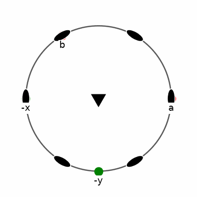
In this first plot, the red \(\vec a\) marker lies at the right, opposite the green \(-\vec x\) marker at the left. This is the \(X\parallel a\) alignment.
cs_y2a = crystalFrame('321', [1.7, 1.7, 1.4], 'Y||a', 'Z||c')
plot(cs_y2a)
annotate(cs_y2a.aAxis, markerFaceColor='r', label='a', backgroundColor='w')
annotate(cs_y2a.bAxis, markerFaceColor='r', label='b', backgroundColor='w')
annotate(-vector3d.Y, markerFaceColor='green', label='-y', backgroundColor='w')
annotate(-vector3d.X, markerFaceColor='green', label='-x', backgroundColor='w')
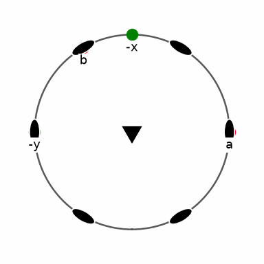
The red lattice-axis markers stay in the same screen positions, but the green Cartesian markers move. Each crystal frame supplies a plotting convention that lays out a crystal plot by its lattice axes.
The transformationMatrix between the two frames exposes the Cartesian offset.
frameOffset = angle(rotation.byMatrix(transformationMatrix(cs_x2a, cs_y2a))) / degree
frameOffset
90
The measured offset is \(90^\circ\). This is a relation between the two Cartesian crystal frames, not a crystal-symmetry operation.
A Plotting Convention Does Not Change the Frame
A plotting convention states how a reference frame is laid out on screen. Changing it moves the markers on the page, but does not change the frame basis, the lattice, or any orientation.
cs_y2a.how2plot.east = cs_y2a.bAxis
plot(cs_y2a)
annotate(cs_y2a.aAxis, markerFaceColor='r', label='a', backgroundColor='w')
annotate(cs_y2a.bAxis, markerFaceColor='r', label='b', backgroundColor='w')
annotate(-vector3d.Y, markerFaceColor='green', label='-y', backgroundColor='w')
annotate(-vector3d.X, markerFaceColor='green', label='-x', backgroundColor='w')
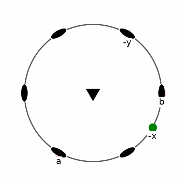
The \(\vec b\) marker now points east and the \(\vec a\) marker has moved. Only the screen layout changed; the \(90^\circ\) frame offset above remains the same.
What the Crystal-Frame Choice Changes
The lattice and its indexed geometry do not change, but their Cartesian coordinates do. Against fixed Cartesian axes, the same indexed quartz shape is therefore expressed differently in the two frames.
cS_x2a = crystalShape.quartz(cs_x2a)
plot(cS_x2a, colored=True)
hold(True)
arrow3d(0.6 * cat(vector3d.X, vector3d.Y, vector3d.Z), labeled=True)
hold(False)
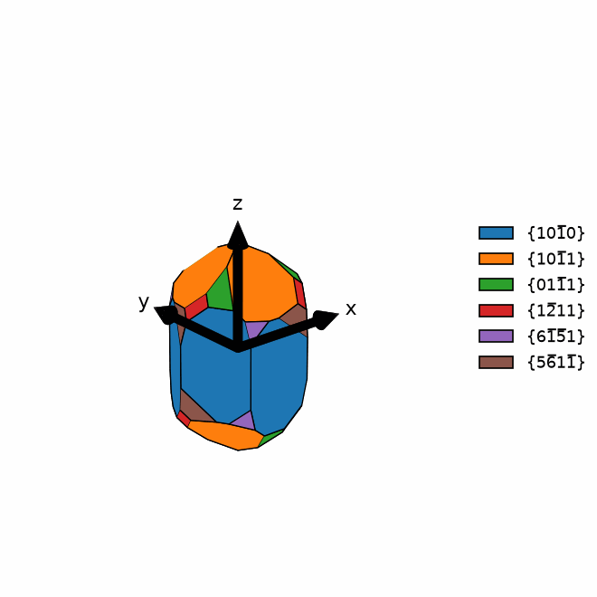
In the \(X\parallel a\) frame, compare the coloured faces with the fixed black \(\vec x\), \(\vec y\), \(\vec z\) arrows.
cS_y2a = crystalShape.quartz(cs_y2a)
plot(cS_y2a, colored=True)
hold(True)
arrow3d(0.6 * cat(vector3d.X, vector3d.Y, vector3d.Z), labeled=True)
hold(False)
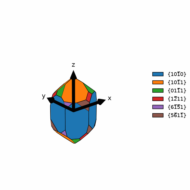
In the \(Y\parallel a\) frame, the same indexed faces occupy different Cartesian positions. The crystal morphology has not changed; only its numerical description relative to the black arrows has changed.
Euler Angles Depend on the Crystal Frame
Euler angles parameterize the map between Cartesian crystal and specimen frames. The same three numbers therefore describe different physical orientations when the crystal frame changes. The two calls below state the Bunge convention explicitly.
ori_x2a = orientation.byEuler(0, 0, 0, 'Bunge', cs_x2a)
ori_y2a = orientation.byEuler(0, 0, 0, 'Bunge', cs_y2a)
newMtexFigure(innerPlotSpacing=20)
plotPF(ori_x2a, Miller(1, 0, 0, cs_x2a), markerSize=20)

nextAxis()
plotPF(ori_y2a, Miller(1, 0, 0, cs_y2a), markerSize=20)
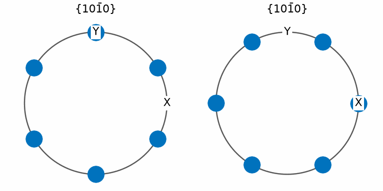
The same indexed pole produces a pattern turned by \(30^\circ\). This is the crystallographic consequence of assigning the same Euler triplet in two different crystal frames.
When the orientations are compared, MTEX reports that it reconciles the differing
frames. The returned value is the smallest difference after applying the 321 crystal
symmetry, not the raw frame offset.
symmetryReducedDifference = angle(ori_x2a, ori_y2a) / degree
symmetryReducedDifference
  The involved symmetries have different reference systems
  1: 321, X||a, Y||b*, Z||c
  2: 321, X||b*, Y||a, Z||c
  I'm going to transform the data from the first one to the second one

30.0000
The symmetry-reduced difference is \(30^\circ\), while the underlying frame offset is \(90^\circ\). Inspecting only symmetry-reduced angles can therefore hide which convention caused an error.
Re-expressing Data in Another Frame
A frame change re-expresses the same physical object in another reference frame. It leaves the object itself untouched and is distinct from rotating it. For orientations, transformReferenceFrame performs that change explicitly.
oriConverted = ori_x2a.transformReferenceFrame(cs_y2a)
oriConverted
orientation (321 → y↑→x)
  Bunge Euler angles in degree
  phi1  Phi  phi2
   270    0     0
The converted Bunge angles are \((270^\circ,0^\circ,0^\circ)\). They differ from the input because the same physical orientation is now expressed in a crystal frame offset by \(90^\circ\).
The indexed direction must nevertheless point to the same specimen direction before and after the frame change.
sameSpecimenDirection = angle(ori_x2a * Miller(1, 0, 0, cs_x2a, 'uvw'), oriConverted * Miller(1, 0, 0, cs_y2a, 'uvw')) < 1e-5 * degree
sameSpecimenDirection
True
The logical result is true. The numerical description changed, but the physical direction did not.
Triclinic and Monoclinic Crystal Frames
A general triclinic or monoclinic lattice has no complete orthogonal triad of direct axes. A Cartesian frame is commonly fixed by aligning one axis with a direct-lattice direction and another with a reciprocal axis. The reciprocal axis is perpendicular to the other two direct axes.
The following two alignments use the same lattice metric. Their displays make the convention part of the audit trail.
cs_aStar2x = crystalFrame('-1', [8.290, 12.966, 7.151], np.array([91.18, 116.31, 90.14]) * degree, 'X||a*', 'Y||b',
                          mineral='An0 Albite 2016')
cs_aStar2x
crystalFrame (⊙c*→b)
  mineral           : An0 Albite 2016
  symmetry          : 1̅
  elements          : 2
  a, b, c           : 8.29, 12.97, 7.151
  alpha, beta, gamma: 91.18°, 116.3°, 90.14°
  reference frame   : X||a*, Y||b
The first summary reports \(X\parallel a^*\) and \(Y\parallel b\).
cs_a2x = crystalFrame('-1', [8.290, 12.966, 7.151], np.array([91.18, 116.31, 90.14]) * degree, 'X||a', 'Z||c*',
                      mineral='An0 Albite 2016')
cs_a2x
crystalFrame (⊙c*→b)
  mineral           : An0 Albite 2016
  symmetry          : 1̅
  elements          : 2
  a, b, c           : 8.29, 12.97, 7.151
  alpha, beta, gamma: 91.18°, 116.3°, 90.14°
  reference frame   : X||a, Z||c*
The second summary reports \(X\parallel a\) and \(Z\parallel c^*\). Whenever orientations or tensor components come from another source, record this alignment with the values. A matching point group alone is not enough.
References
- U. Shmueli, Reciprocal space in crystallography, International Tables for Crystallography B, ch. 1.1, 2006, constructs Cartesian bases from direct and reciprocal lattice vectors.
- D. Rowenhorst et al., Consistent representations of and conversions between 3D rotations, Modelling and Simulation in Materials Science and Engineering 23, 083501, 2015, explains why frame and rotation conventions must be stated explicitly.
- J. F. Nye, Physical Properties of Crystals: Their Representation by Tensors and Matrices, corrected paperback ed., Oxford University Press, 1985, develops Cartesian tensor components and crystallographic symmetry.
- ASTM E82/E82M-14(2019) defines a measured crystal orientation relative to specimen geometry.
Next
Crystal Axes Alignment shows how published data are converted when sources name or permute lattice axes differently. Orientations as Coordinate Transforms then develops the map from a crystal frame to a specimen frame. Importing Tensor Data applies the same audit to published component tables.
Technical Details
A crystal frame is an interned handle: two frames of one lattice and alignment are the
same object, and the alignment string of the display is derived from the basis, not
stored. Comparing orientations in differently aligned frames of one group re-expresses
the first in the frame of the second and says so, as MATLAB’s ensureCS does; frames of
different groups or metrics are refused.
Citing this page.
This page is part of the documentation of
MTEX, a free and open
source MATLAB toolbox for analyzing and modeling crystallographic textures.
It was written by The MTEX Developers and is published at
https://mtex-toolbox.github.io/CrystalReferenceSystem_py.html.
If you use MTEX, or reuse text or figures from this page, in your research,
please cite
F. Bachmann, R. Hielscher, H. Schaeben: Texture Analysis with MTEX - Free and Open Source Software Toolbox, Solid State Phenomena 160 (2010), 63-68. 10.4028/www.scientific.net/SSP.160.63
BibTeX
@article{bachmann2010mtex,
  author  = {F. Bachmann and R. Hielscher and H. Schaeben},
  title   = {Texture Analysis with MTEX - Free and Open Source Software Toolbox},
  journal = {Solid State Phenomena},
  volume  = {160},
  pages   = {63-68},
  year    = {2010},
  doi     = {10.4028/www.scientific.net/SSP.160.63},
  url     = {https://doi.org/10.4028/www.scientific.net/SSP.160.63}
}
Other papers describing specific MTEX methods are listed under Publications — please cite the one that best fits your application. The MTEX source code is licensed under the GNU General Public License v2.0; the text and figures of this documentation are licensed under CC BY 4.0, which permits reuse — including by automated systems — provided The MTEX Developers and this page are credited.