
Authors: Vivian Tong; Stefan Olovsjö, Seco Tools AB, R&D Materials and Technology, 737 82 Fagersta, Sweden. Contact: vivian.tong@extern.tu-freiberg.de
Sometimes the EBSD map and the SEM images are not stored the same way round. Rotate the stage between two acquisitions, load a map from software that writes its scan lines in the other direction, or import images taken in a separate session, and the two no longer agree about which way the sample points.
TrueEBSD will not guess at this, because guessing wrong does not fail loudly — the matching still runs, still fits, and hands back a finished-looking result that is quietly nonsense. So it asks, and this page shows how to answer.
The short WC-Co page is the ordinary case, where everything was collected in one session and there is nothing to say. Read that one first; this page is the same workflow with one extra step.
This script needs the TrueEBSD toolbox, which is not part of MTEX and is distributed separately under Apache-2.0: https://github.com/vtvivian/mtex-trueebsd
addpath(genpath('<path to mtex-trueEbsd>'))The data
The same cut-down WC-Co dataset as the short page: an EBSD map and four SEM images of the same area.
No plotting convention is set here. A convention decides how things are drawn; it has no bearing on how they are stored, and it is the storage that matters when two pictures are compared pixel by pixel.
mtexdata trueEbsdWCCoSmall

img = ebsd.opt.trueEbsdImgs;
img.fsdB3  = rescale(imboxfilt(img.fsdB3,3));
img.fsdT3  = rescale(imboxfilt(img.fsdT3,3));
img.fsdT1  = rescale(imboxfilt(img.fsdT1,3));
img.fsdT10 = rescale(imboxfilt(img.fsdT10,3));
ebsd = EBSDsquare (y↓→x)
Phase Orientations Mineral Color Symmetry Crystal reference frame
0 89 (0.72%) notIndexed none
1 11180 (91%) W C LightSkyBlue -6m2 X||a*, Y||b, Z||c
2 991 (8.1%) Co-fcc DarkSeaGreen m-3m
3 28 (0.23%) Co-hcp Goldenrod 6/mmm X||a*, Y||b, Z||c
Properties: bc, bs, bands, MAD, quality, oldId
Scan unit : um
X x Y x Z : [10 → 30] x [8 → 23] x [0 → 0]
Normal vector: (0,0,1)
Square grid :96 x 128
source: trueEbsdWCCo, centre half of the field of view, coarsened 4x
madeBy: trueEBSD tools/makeWCCoSmall.mTurn the map, to have something to fix
To get a map and images that disagree, turn the map through 90°. This is what a stage rotation between acquisitions would leave you with: the map now shows the specimen at right angles to what the detectors saw.
rot90z = rotation.byAxisAngle(zvector,90*degree);
ebsdRot = gridify(rotate(ebsd,rot90z),'force');
Build the sequence
Exactly as on the short page. Nothing here mentions the rotation — as far as this code knows, these are just five pictures of one sample.
imgList = createArray(5,1,'distortedImg');
imgList(1) = distortedImg('bc','shift-drift', ebsdRot, 'name','bcImg', ...
  'highContrast',1, 'edgePadWidth',3);
imgList(2) = distortedImg(img.fsdB3, 'true',  'dxy', img.pixSzImg, 'name','fsdB3',  'highContrast',1, 'edgePadWidth',5);
imgList(3) = distortedImg(img.fsdT3, 'shift', 'dxy', img.pixSzImg, 'name','fsdT3',  'highContrast',1, 'edgePadWidth',5);
imgList(4) = distortedImg(img.fsdT1, 'tilt',  'dxy', img.pixSzImg, 'name','fsdT1',  'highContrast',1, 'edgePadWidth',5);
imgList(5) = distortedImg(img.fsdT10,'true',  'dxy', img.pixSzImg, 'name','fsdT10', 'highContrast',1, 'edgePadWidth',3);
Plotting the sequence shows the problem at once: the EBSD map is on its side relative to the four images.
plot(imgList)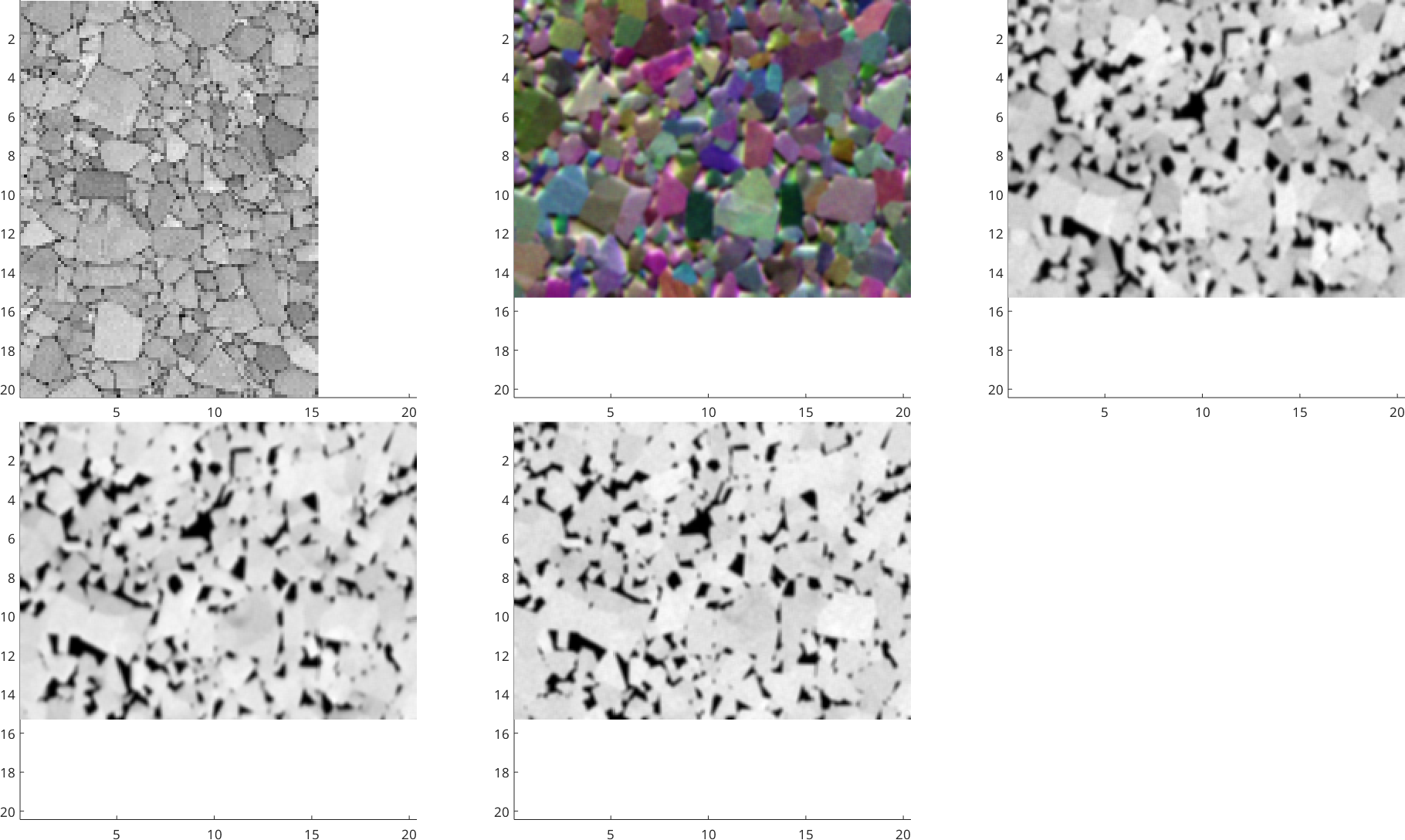
Fix it by telling TrueEBSD how the map is oriented. Each entry is drawn the way its own frame says it should be, so changing the map's frame changes what you see — turn it until the plots agree with each other. Here the map needs 'x↑→y'; the images keep the default.
This is the part only you can supply. It is a fact about how the data was collected, and no amount of looking at the numbers will recover it.
ebsdFrame = imgList(1).frame;
ebsdFrame.how2plot = 'x↑→y';
plot(imgList)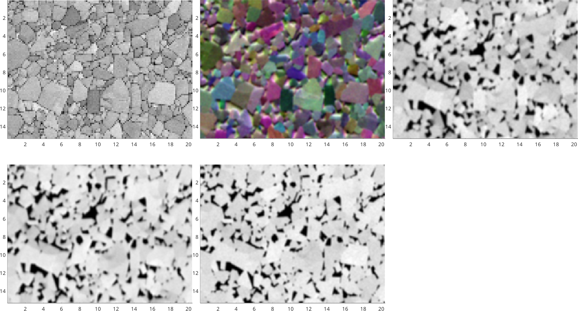
All five now agree on screen, which is the assertion TrueEBSD needs. 'byScreenAlignment' means exactly that: I have plotted these and they are the same way up. transformReferenceFrame takes that statement and restates all five in one frame, so they can be compared.
imgList = imgList.transformReferenceFrame(ebsdFrame, 'byScreenAlignment')imgList = distortedImg (x↑→y)
image pixel frame distortion contrast EBSD
1 96 x 128 0.16 µm x↑→y shift-drift high W C, Co-fcc, Co-hcp
2 192 x 256 x 3 0.08 µm x↑→y true high -
3 192 x 256 0.08 µm x↑→y shift high -
4 192 x 256 0.08 µm x↑→y tilt high -
5 192 x 256 0.08 µm x↑→y true high -Run the workflow
From here nothing is different. The sequence is in one frame, so the rest is the ordinary workflow — see the short page for what each step does.
job = trueEbsd(imgList);
job.pixelSizeMatch(0)

nRows = size(job.resizedList(1).img,1);
nCols = size(job.resizedList(1).img,2);

for n = 1:numel(job.resizedList)
  for m = 1:numel(job.resizedList(n).setXCF)
    job.resizedList(n).setXCF(m).ROISize  = 64;
    job.resizedList(n).setXCF(m).NumROI.x = 16;
    job.resizedList(n).setXCF(m).NumROI.y = round(16 * nRows/nCols);
  end
end

job.resizedList(5).setXCF(1).ROISize = 0;
for n = 3:5
  job.resizedList(n).setXCF(1).xcfImg = 'img';
end

job.calcDistortion('fitErr')
using default pixel size of 0.079501 um, minimum from imgList
ans = trueEbsd (pixel size matched)
image distortion shift residual
1 192 x 256 shift-drift - -
2 192 x 256 x 3 true - -
3 192 x 256 shift - -
4 192 x 256 tilt - -
5 192 x 256 true - -
common grid: 192 x 256 at 0.08 µm
fitting the distortion across 5 maps, 4 hops
hop distortion model ROI shift residual
2→1 shift-drift poly11 64 px 3.73 px
linearinterp 64 px 1.83 px
after fitting 1.61 px
3→2 true not correlated - 0.00 px
not fitted 1.52 px
4→3 shift poly11 64 px 3.18 px
Warning: Iteration limit reached for robust fitting.
after fitting 0.33 px
5→4 tilt projective 64 px 3.63 px
poly11 64 px 0.44 px
poly22 64 px 0.31 px
after fitting 0.31 px
ans = trueEbsd (shifts calculated)
image distortion shift residual
1 192 x 256 shift-drift 1 px 1.6 px
2 192 x 256 x 3 true 0 px 1.5 px
3 192 x 256 shift 3.2 px 0.33 px
4 192 x 256 tilt 0.34 px 0.31 px
5 192 x 256 true - -
common grid: 192 x 256 at 0.08 µmjob.undistort
plot(job.undistortedList,'TrueEBSD image sequence after alignment')ans = trueEbsd (undistorted)
image distortion shift residual
1 192 x 256 shift-drift 1 px 1.6 px
2 192 x 256 x 3 true 0 px 1.5 px
3 192 x 256 shift 3.2 px 0.33 px
4 192 x 256 tilt 0.34 px 0.31 px
5 192 x 256 true - -
common grid: 192 x 256 at 0.08 µm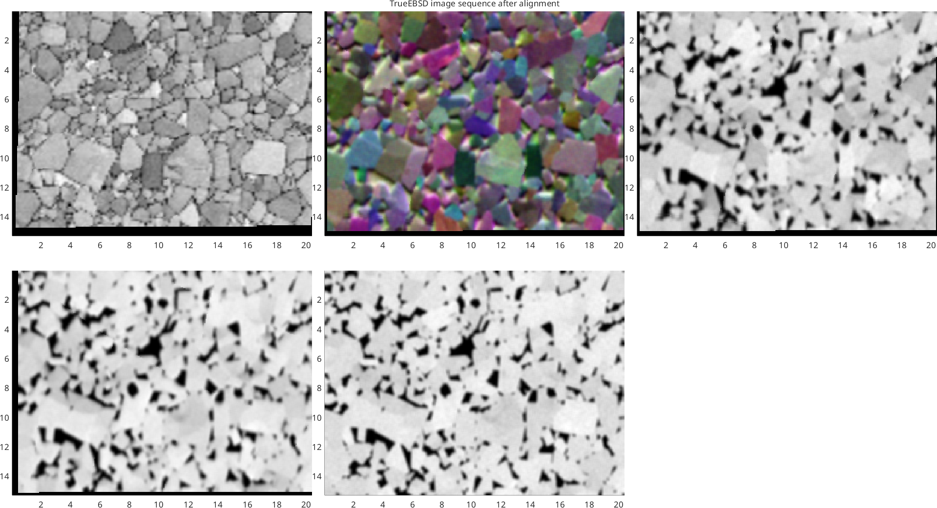
Check the result
The aligned images are properties of the map, exactly as on the short page.
The map and the images come out the same way round and the same shape. That is the point of having said which frame everything is in: gridify takes a layout, so the map is rebuilt in the frame you asked for rather than in MTEX's standard one, and ebsd.bc can then be put beside an aligned image pixel for pixel with nothing in between.
ebsdOut = job.undistortedList(1).ebsd;

fprintf('aligned image: %d x %d\n', size(job.undistortedList(1).img,1), size(job.undistortedList(1).img,2));
fprintf('EBSD object  : %d x %d\n', size(ebsdOut,1), size(ebsdOut,2));

figure
nextAxis
plot(ebsdOut('W C'), ebsdOut('W C').orientations, 'coordinates','on')
title('Undistorted MTEX EBSD map (WC IPF out of screen)','Color','k')

nextAxis
im = ebsdOut.fsdT1;
if size(im,3) > 1, im = mean(im,3); end
plot(ebsdOut, im, 'coordinates','on')
mtexColorMap gray
title('Undistorted fsdT1','Color','k')
aligned image: 192 x 256
EBSD object : 192 x 256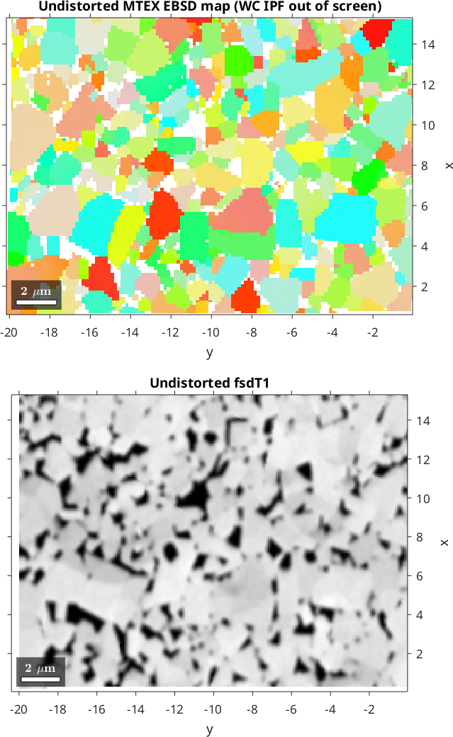
The real test is whether the alignment worked. Compare the map's band contrast against the image aligned to it — they should track each other closely, and they do, just as well as on the short page where no rotation was involved. Saying which way round the map was cost nothing in quality; it only made an otherwise impossible case possible.
a = double(ebsdOut.bc);
b = double(job.undistortedList(1).img);
k = isfinite(a) & isfinite(b) & a > 0;
r = corrcoef(a(k),b(k));
fprintf('corr(ebsd.bc, aligned image) = %.4f\n', r(1,2));
corr(ebsd.bc, aligned image) = 0.9309Finish
Everything this page added to the short workflow was two lines: turning the map's frame until the plots agreed, and one call to transformReferenceFrame to say so. The sequence, the distortions, the box settings and the result are identical.
If your map and images were collected the same way up you need none of it. Reach for this when the plots disagree, or when building the job stops with trueEbsd:frameMismatch — which is TrueEBSD telling you it has spotted the problem rather than guessing past it.
Citing this page.
This page is part of the documentation of
MTEX, a free and open
source MATLAB toolbox for analyzing and modeling crystallographic textures.
It was written by The MTEX Developers and is published at
https://mtex-toolbox.github.io/example_WCCoFrames.html.
If you use MTEX, or reuse text or figures from this page, in your research,
please cite
F. Bachmann, R. Hielscher, H. Schaeben: Texture Analysis with MTEX - Free and Open Source Software Toolbox, Solid State Phenomena 160 (2010), 63-68. 10.4028/www.scientific.net/SSP.160.63
BibTeX
@article{bachmann2010mtex,
  author  = {F. Bachmann and R. Hielscher and H. Schaeben},
  title   = {Texture Analysis with MTEX - Free and Open Source Software Toolbox},
  journal = {Solid State Phenomena},
  volume  = {160},
  pages   = {63-68},
  year    = {2010},
  doi     = {10.4028/www.scientific.net/SSP.160.63},
  url     = {https://doi.org/10.4028/www.scientific.net/SSP.160.63}
}
Other papers describing specific MTEX methods are listed under Publications — please cite the one that best fits your application. The MTEX source code is licensed under the GNU General Public License v2.0; the text and figures of this documentation are licensed under CC BY 4.0, which permits reuse — including by automated systems — provided The MTEX Developers and this page are credited.